Copper-Nickel Mineralization in a Drill Core From the Duluth Complex of Northern Minnesota
By Michael L. Boucher
Twin Cities Metallurgy Research Center, Twin Cities, Minn.
1975
UNITED STATES DEPARTMENT OF THE INTERIOR
Kent Frizzell, Acting Secretary
Jack W. Carlson, Assistant Secretary-Energy and Minerals
BUREAU OF MINES
Thomas V. Falkie, Director
This publication has been cataloged as follows:
Boucher, Michael L
Copper-nickel mineralization in a drill core from the Duluth Complex of northern Minnesota. [Washington] U.S. Bureau of Mines [1975]
55 p. illus., tables. (U.S. Bureau of Mines. Report of investigations 8084)
Includes bibliography.
1. Copper ores-Minnesota. 2. Nickel ores-Minnesota. I. U.S. Bureau of Mines. II. Title. (Series)
TN23.U7 no. 8084 622.06173
U.S. Dept. of the Int. Library
CONTENTS Page
Abstract
.............................................................................................1
Introduction
......................................................................................1
Acknowledgments ..............................
..............................................4
Rock descriptions
............................................................................4
Igneous rocks
....................................................................................8
Troctolite
.........................................................................................10
Anorthosite
.......................................................................................10
Mafic pegmatite and gabbro
............................................................13
Picrite
................................................................................................13
Rock inclusions
................................................................................13
Opaque minerals
.................................................................................20
Pyrrhotite-troilite
...............................................................................23
Pentlandite
..........................................................................................28
Chalcopyrite-cubanite
........................................................................30
Mineralization and paragenesis
..........................................................34
Summary
...............................................................................................39
Bibliography
.........................................................................................40
Maps
......................................................................................................46
Appendix
...............................................................................................47
ILLUSTRATIONS
1. The Duluth Complex, northern Minnesota
......................................2
2. Generalized geologic drill log of DDH-IA
.....................................5
3. Plot of modal analyses of rock thin sections from DDH-IA
for the
three major rock-forming minerals, their alteration products, and
total opaque minerals
.............................................................................6
4. Rock classification chart
...................................................................9
5. Plot of samples from DDH-IA
..........................................................9
6. Troctolite
...........................................................................................11
7. Anorthosite
........................................................................................12
8. Mafic pegmatite
................................................................................14
9. Picrite
.................................................................................................15
10. Hornfels
...........................................................................................16
11. Basalt hornfels
.................................................................................17
12. Biwabik Iron Formation
..................................................................18
13. Magnetite hornfels
..........................................................................19
14. Composite sulfide grain
..................................................................21
15. Composite sulfide grains connected by veinlets ....
......................22
16. Chalcopyrite filling open space
......................................................22
17. Composite oxide grain
.....................................................................24
18. Oxide exsolution texture
..................................................................24
19. Pyrrhotite-troilite grain showing complex exsolution
..................25
20. Pyrrhotite-troilite intergrowth
.........................................................25
21. Pyrrhotite islands in chalcopyrite
....................................................26
22. Patchy replacement of pyrrhotite by
chalcopyrite-cubanite
intergrowth
................................................................................................26
23. Alignment of troilite in pyrrhotite surrounded by
chalcopyrite ....27
ii
ILLUSTRATIONS - -Continued
Page
24. Detail of troilite-pyrrhotite cut by chalcopyrite
...........................27
25. Chalcopyrite-cubanite invading pentlandite along
cleavage direc-
tions, grain boundaries
...........................................................................29
26. Almost complete replacement of pentlandite by
chalcopyrite-
cubanite
...................................................................................................29
27. Chalcopyrite-cubanite intergrowths
...............................................31
28. Cubanite lamellae showing patchy extinction
...............................31
29. Chalcopyrite-bornite intergrowths
.................................................32
30. Sphalerite star in chalcopyrite-cubanite
........................................32
31. Mackinawite replacing chalcopyrite
..............................................33
32. Replacement of oxides by chalcopyrite-cubanite
.........................33
33. Plot of sulfides from the major mineralized zone of
DDH-IA ...36
TABLES
1. Opaque mineral content in major mineralized zone, DDH-IA .......35
A-l. Modal analyses of rocks from DDH-IA .......................................54
COPPER-NICKEL MINERALIZATION IN A DRILL CORE
FROM THE DULUTH COMPLEX
OF NORTHERN MINNESOTA
by
Michael L. Boucher1
Copper and nickel sulfides occurring in the Duluth Complex of northern Minnesota were examined at the Bureau of Mines. A microscopic study was undertaken to determine the mineralogy and paragenesis of the ore minerals. Eighty-two samples were taken from one deep diamond drill core located near Babbitt, Minn. Modal analyses are presented for the Duluth Complex rocks and for the ore minerals in the major mineralized zone. The major sulfide minerals are chalcopyrite, cubanite, pyrrhotite, troilite, and pentlandite. Results of this investigation suggest that the mineralization is related to the structural features of the enclosing rocks: pores, open fractures, and cavities. The pyrrhotite-troilite-pentlandite assemblage is believed to have formed from an immiscible sulfide melt, probably associated with the troctolitic rocks. Most of it settled to the very porous base of the Duluth Complex, and to the other porous zones near xenoliths; small portions were trapped higher in the section. A later introduction of a copper-rich sulfide melt replaced some of the pyrrhotite-troilite and oxides, and filled in the remaining open spaces and fractures in the Duluth Complex and those of the adjacent footwall rock.
This investigation was initiated to obtain geologic information on the Duluth Complex of northern Minnesota that would help to characterize the potential of its copper and nickel mineralization. The project was designed to assist metallurgical and beneficiation studies being done both by the Bureau of Mines and private companies on ore samples from the Duluth Complex.
The Duluth Complex (fig. 1) is a large composite igneous intrusive of Late Precambrian age, about 1.1 billion years (20).2 it outcrops in a crescent-shaped pattern extending northward from Duluth for 130 miles to north of Grand Marais; the Duluth Complex is 40 miles across at its widest point (68). It is bordered on the east by the North Shore Volcanic Group of Late Precambrian Keweenawan age; on the west, it intrudes and cuts off older
___________________________________________________________________________________________________________
1 Geologist
2 Underlined numbers in parentheses refer
to items in the bibliography preceding the appendix.
2
3
metasedimentary rocks and granites. The Duluth Complex dips gently southeast toward Lake Superior. Sims (59) suggests that it was probably intruded along an unconformity between the overlying volcanics and the underlying older Precambrian rocks.
The mineralization of commercial interest in the Duluth Complex has been described by other investigators as a disseminated deposit of copper and nickel sulfide ore, mostly confined to the area near the base of the Duluth Complex (2, 9-10, 32, 56, 59, 68). The ore zones are reported to be from 50 to 300 feet in aggregate thickness (2), and to occur in discontinuous zones or pods of mineralized troctolite and gabbro. Although many assays have been published, some exceeding 1 percent copper and 0.3 percent nickel (21, 56), the ore grades for large tonnages are marginal and will probably average 0.3 to 0.4 percent copper and 0.12 percent nickel. Assays representative of bulk ore tonnages have been reported by several investigators (10, 33-34, 65-67). The Minnesota Geological Survey has estimated the resource at 5-1/2 billion tons of ore with a cutoff grade of 0.25 percent combined copper and nickel yielding 22.4 million tons of copper and 7.5 million tons of nickel (10, 61).
Other metals occurring in the Duluth Complex that may be economically recoverable in addition to the copper and nickel are cobalt, titanium, aluminum, gold, silver, platinum, palladium, and rhodium, with the possibility of other platinum-group metals. Trace amounts of vanadium, chromium, zinc, lead, and molybdenum have been reported in the ores.
The Bureau of Mines made an initial evaluation of the copper and nickel potential of the Duluth Complex in conjunction with (21). The assays, originally more than 1 percent combined copper and nickel at the surface in shallow drill holes and test pits, dwindled rapidly to 0.5 percent and less with depth. Some oxidation of the sulfides and formation of malachite or other secondary minerals probably caused the enrichment near the surface. Flotation and other separation techniques were investigated, but the major problems were the low tenor of the ore and the difficulties in producing separate copper and nickel sulfide concentrates.
Recent beneficiation tests made on the ore by the Mineral Resources Research Center at the University of Minnesota (formerly the Mines Experiment Station) (65-67) and the Bureau of Mines Twin Cities Metallurgy Research Center gave results essentially the same as those found in a 1955 Bureau study (21). Copper could be recovered up to 98 percent, but the nickel recovery ranged from 50 to 85 percent, depending on the type of ore. Further, after differential flotation treatment, analysis of the copper concentrate showed 25 to 30 percent copper with 0.9 percent nickel, whereas the nickel concentrate contained about 1.5 percent nickel and over 10 percent copper (65). A differential float is no longer being attempted; instead, the bulk float product is being used as the takeoff point for other extractive metallurgical methods. Recently, further research has been initiated by the Bureau to solve some of these problems and still allow extraction to be economically feasible.
4
A number of papers and graduate theses have been written on various aspects of the Duluth Complex, including a few on the economic geology of these deposits. The bibliography contains a fairly comprehensive list of papers written on the Duluth Complex. Geologic and geophysical maps in varying detail are available for much of the area and are included in a separate list at the end of the bibliography.
This report presents the results of examining one deep diamond drill core from an area south of Babbitt, Minn. Although the details are from only one hole, most of the relations described here have been observed in rocks from other areas in the complex.
The author wishes to thank Bill Bonnichsen, Cornell University, James J. Sjoberg, Bureau of Mines Reno Metallurgy Research Center, Reno, Nev., and Paul W. Weiblen, Minnesota Geological Survey for reviewing the original paper, and Paul K. Sims and William C. Phinney (both formerly with the Minnesota Geological Survey), for helpful discussions about the rocks and their mineralization.
Diamond drill hole IA, which is located south of Babbitt, Minn., is approximately vertical and 2,950 feet deep. The collar is several miles from the contact of the Duluth Complex with the Biwabik Iron Formation and the Virginia Formation. The exact location of these contacts is somewhat questionable. The dip of the Duluth Complex in this area is estimated to be about 30° southeast. The overburden is about 20 feet thick in the area of the drill hole, and outcrops are scattered.
Eighty-two pieces of core were taken as samples, representing both the mineralized and the unmineralized portions of the core. Descriptions of the texture and grain sizes of each of these are included in the appendix. Drill logs of the hole were provided by the exploration company for which the hole was drilled. Figure 2 is a generalized graphic log of the drill core.
Thin sections made from each sample were taken perpendicular to the core axis and two sections each were taken from those few cores where a change was noted within the core. Point counts of the major minerals (900 to 1,500 counts per section) were made on most of the thin sections to obtain modal analyses for classifying the rocks. Replication of the point counts on a few medium-grained samples traversing different paths from the original count gave less than a 2-percent difference on the major (>10 percent) components, and less than 1 percent on the minor (<10 percent) components. The rock grain size ranges from less than 1 millimeter to greater than 5 centimeters, and the error of the mode is smaller for the fine-grained rocks and greater for the coarse-grained and pegmatitic rocks. The actual area counted of each thin section ranged from 2 to 3/4 square inch. For the coarse-grained rocks (pegmatites), this was not a sufficient sample area to be representative of the actual rock mode. The core was less than
5
FIGURE 2. - Generalized geologic drill log of DDH-IA. Rocks too thin to be plotted at this scale are represented by three symbols and a bar on each side indicating the approximate depth. The zone just above 2,000 feet is a zone of thin, alternating picrite and troctolite, hence the use of both symbols. Sulfide mineralization is indicated by a dot overprint; thin occurrences are indicated by a horizontal line of dots. Percentages indicated along the side of the mineralized zones are visual estimates of the combined weight-percent of Cu and Ni in each zone.
6-7
8
1-1/2 inches in diameter and severely limited the sample area at a given horizon. Modes of the pegmatites should therefore be considered only grossly indicative of the actual mode. Excluding the pegmatites, most of the modes seem to be reasonable estimates of the rock compositions. (See fig. 3.)
Opaque minerals are not accurately represented when using thin sections for counting since what is seen is the maximum diameter of the opaque, not the intersection of the opaque with the upper plane surface. The inflated thin section values for the opaques are reported in table A-l and plotted in figure 3. However, polished sections were used to determine the values reported later in table 1 and for the data plotted in figure 33 for the major sulfide zone.
Results of the modal analyses showed that a majority of samples were troctolites. Occasional lenses of anorthosite, mafic pegmatite, gabbro, and picrite were also present. Several intersections of recrystallized metasediments and basalts were seen throughout the core and are described under "Rock Inclusions." The Virginia Formation was recognizable at 2,846 feet, and the Virginia-Biwabik contact was noted at 2,916 feet. These rocks were not point counted, but descriptions are found in the appendix.
The modes are plotted in two different ways. Figure 3 is a three-part bar graph with plagioclase-sericite plotted on the right; the major mafics, olivine and pyroxene and their alteration products serpentine and amphibole, are plotted in the middle; and the oxide-sulfide (opaques) values from thin-section data are plotted on the left. Vertical lines are drawn at percentages, which are major breaks in most rock classification schemes. Figure 4 shows a rock classification chart proposed for these rocks by Phinney (43). The three major components, plagioclase, olivine, and pyroxene are recalculated to 100 percent and plotted to obtain the rock name. These names are used in table A-l in the appendix, which lists all the modal data. Figure 5 is a plot, using this scheme, of all the rocks from DDH-IA believed to be igneous in origin and shows the range of composition. The alteration products are included; for example, serpentine is included in the value for olivine, etc.
The major variables in this core are texture and olivine content. Troctolite is the main rock type, but variations in the olivine content give rock types ranging from picrite to anorthosite. Using Phinney’s subgroups (fig. 4), rocks of the troctolite affinity range from picrite to troctolitic anorthosite. The true anorthosites, which are older than the troctolites, are typically coarse grained with moderate sericitic alteration.
Note that in figure 5 most of the rocks are either 10 percent or less pyroxene (that is, in the troctolite range) or 10 percent or less olivine (that is, in the gabbro range). Most of the gabbroic rocks are mafic pegmatites. The one rock plotted near the bottom of the diagram (wehrlite) is fairly coarse grained and probably would have occurred in the gabbro field if the sample had been more representative. It is included with the gabbro on the drill log (fig. 2).
9
FIGURE 4. - Rock Classification Chart. Three components are recalculated to 100 percent (43).
Generally, contacts between these rocks were sharp and easily noted, such as those between troctolite and anorthosite. However, some contacts were more gradational, such as those between troctolite and anorthositic troctolite, where the amount of olivine would change over 1 foot or more. Contacts between troctolite and picrite were sometimes sharp and sometimes gradational even within the same general zone. The mixed picrite-troctolite zone between 1,955 and 2,000 feet is a series of bands of picrite alternating with troctolite; both sharp and gradational contacts are noted. The contact at the base of the Duluth Complex is actually a zone about 100 feet or more thick of mixed hornfels and fine-grained troctolite. Contacts between the two become unclear in an intermediate zone of troctolite contaminated with metasediments and partially melted hornfels infiltrated with fine-grained troctolite.
Layering is noted in several places (68), but is discontinuous and may be due to local trapping of the liquid magma in low areas. Bonnichsen (4) has suggested that multiple intrusions of troctolitic magma occurred after the anorthositic rocks were emplaced. This theory accounts for the many alternating zones of troctolite and anorthosite, the lack of good chill zones, the range of troctolitic compositions,
10
and the lack of any large-scale layering. Although this hole does not show many changes in rock types associated with typical layering, it does show the aforementioned alternating picrite and troctolite zones.
The troctolites are medium- to fine-grained rocks with all gradations of composition present from anorthositic troctolite to picrite. Plagioclase laths and rounded olivines occur as primary cumulate minerals (fig. 6). The range of grain sizes for most of the minerals is quite large (<0.1 to >10 millimeters) and more than one generation of cumulate olivine is occasionally seen. Olivines occur singly or in chains, and are sometimes included or partially enclosed by larger plagioclase laths. Alternately, some olivines contain small feldspar crystals within their centers, and show radial shrinkage cracks in the olivine around the crystal.
The plagioclase is lath-shaped with ubiquitous albite and carlsbad twinning. Zoning is also quite common, particularly in the larger feldspar grains; however, no determination of the anorthite compositions were made for these rocks. (See Phinney for plagioclase compositions found in the Gabbro Lake area (41). Many of the plagioclase grains exhibit some schiller structure, and the cores frequently contain more ilmenite than the rims.
The pyroxenes demonstrate a typical anhedral-interstitial to ophitic texture and commonly form partial coronas around olivines. Most pyroxenes are augite or pigeonite, zoned, and contain ilmenite schiller and biotite. Some are completely filled with biotite and ilmenite. Biotite crystals at the pyroxene margins were observed extending into adjoining plagioclase grains. Hardyman (28) reported the same relations in his study of Duluth Complex rocks. Hypersthene is present but is less common in the igneous rocks here than has been reported in the Duluth complex by other authors (2, 4). Occasional large crystals of orthopyroxene with augite lamellae (possibly an inverted pigeonite) have been seen, but few occurrences of late interstitial or fibrous orthopyroxene were noted in these rocks. Appendix table A-l lists separately the amounts of orthopyroxene.
The anorthosite is composed primarily of subhedral, medium- to coarse-grained (1 to 30 millimeters), cumulate plagioclase with occasional grains of interstitial pyroxene or olivine. Plagioclase is lath-shaped with albite and carlsbad twinning. Zoning is quite common, and many plagioclase cores contain ilmenite schiller (fig. 7). Although no work was done in this study to check variations in the anorthite composition of the plagioclase zones, a comparison of zoning patterns in plagioclases of the various rocks might be important in determining whether rocks of intermediate compositions were derived from original troctolitic or anorthositic intrusives. Much of the plagioclase in the anorthosite is slightly sericitized, giving a "soft texture" look to the grain boundaries megascopically.
11
FIGURE 6A. - Troctolite, medium-grained, 42.0 feet; transmitted light (X 7). Rounded olivine (gray, fractured) and plagioclase laths (white background);
FIGURE 6B. - Troctolite, medium-grained, 42.0 feet; transmitted light (X 7). Crossed polars, striped phase is twinned plagioclase.
12
FIGURE 7A. - Anorthosite, coarse-grained, 203.0 feet; transmitted light (X 7). Coarse plagioclase laths (shades of light gray), with minor interstitial, schiller-filled clinopyroxene (dark gray).
FIGURE 7B. - Anorthosite, coarse-grained, 203.0 feet; transmitted light (X 7). Crossed polars, striped phase is twinned plagioclase.
13
The mafic pegmatites are very coarse grained (up to 10 centimeters) and usually are composed of subhedral plagioclase, very large rounded pyroxenes and occasional rounded olivine grains. The mafic pegmatites can usually be classified as gabbros or olivine gabbros. They have relatively short lateral continuity in outcrop and usually cannot be traced to adjacent drill holes (68). The pyroxene is usually augite, pink to brown, in thin section, and filled with ilmenite schiller and biotite. It appears almost poikilitic because of the large amounts of biotite and ilmenite. Pyroxenes are normally flattened and elongated, and oriented parallel to a particular direction in the rock. Some of the deep-pink pyroxenes were found to be pigeonites, but others were indeterminate due to interference by the large concentration of schiller inclusions. The plagioclase laths are broad, and twinning and zoning are common. Schiller is present to such a degree in the plagioclase that many of the grains are nearly black in hand specimen (fig. 8). Typically, many of the pegmatites are mineralized with chalcopyrite-cubanite intergrowths, and quartz and calcite are occasionally present when the rock is altered. Alteration products are usually sericite, tremolite, prehnite, and, if olivine is present, serpentine.
The picrites occur in layers a few feet thick, or alternate with troctolite in zones. These zones are similar to Wager’s "layered series" (68). The picrites typically have cumulate olivine, with plagioclase somewhat anhedral and interstitial, to an almost poikilitic texture with respect to the olivine grains. The olivines are usually large and, under crossed polars, show up as chains or elongate groups of smaller beady grains, many with mutual boundaries (fig. 9). Many olivines in these rocks, as in those rocks described earlier, have rounded plagioclase grains at their centers and show radial fracturing outward from the enclosed plagioclase. The included plagioclase grains are very similar to those described earlier, although they do not have the anhedral interstitial texture. Most of the picrites are altered; serpentine and sericite are the most common alteration products.
Numerous rock inclusions are known in the Duluth Complex, and several sections were noted in the core samples. Most inclusions are readily identified by their texture or composition; however, some are not so obvious, having been recrystallized or mixed with the intrusives. Typically, the inclusions are finer grained than the Duluth Complex intrusives and show relict volcanic or sedimentary textures. The most common types are hornfels, believed to be recrystallized greenstone or Virginia Formation (argillite), and xenoliths of recrystallized Biwabik Iron Formation (figs. 10-13). One small section of coarse-grained granite was noted at 1,030 feet.
14
FIGURE 8A. - Mafic pegmatite, 932.9 feet; transmitted light (X 7). Coarse-grained laths of plagioclase (sericitized, white phase), large irregular olivines (medium gray with irregular fractures), and schiller-filled interstitial clinopyroxene (medium to dark gray with black parallel lines). Black grains are ilmenite-magnetite.
FIGURE 8B. - Mafic pegmatite, 932.9 feet; transmitted light (X 7). Crossed polars, striped phase is twinned plagioclase.
15
FIGURE 9A. - Picrite, medium-grained, 845.5 feet; transmitted light (X 7). Rounded olivines (dark gray, fractured) with lathy plagioclase (light gray background). Some oxides (black) and interstitial schiller-filled clinopyroxene (notable in upper left quadrant, similar in appearance to ohvine).
FIGURE 9B. - Picrite, medium-grained, 845.5 feet; transmitted light (X 7). Crossed polars, striped phase in twinned plagioclase.
16
FIGURE 10A. - Hornfels, fine-grained, 2,845.9 feet; transmitted light (X 7). Irregular plagioclase (light gray) with poikilitic clinopyroxenes and rounded ohvine (both dark gray), black grains are oxides.
FIGURE 10B. - Hornfels, fine-grained, 2,845.9 feet; transmitted light (X 7). Crossed polars, striped phase is twinned plagioclase.
17
FIGURE 11A. - Basalt hornfels (porphyritic), fine-groined, 2,333.2 feet; transmitted light (X 7). Phenocrysts of zoned plagioclase (light gray) in groundmass of plagioclase (light gray) and clinopyroxene (dark gray), black grains are oxides.
FIGURE 11B. - Basalt hornfels (porphyritic), fine-groined, 2,333.2 feet; transmitted light (X 7). Crossed polars. Note plagioclase phenocrysts in upper left and lower right quadrants (white and dark gray).
18
FIGURE 12A. - Biwabik Iron Formation, fine to medium -grained, banded iron formation; 2924.6 feet; transmitted light (X 7). Quartz (white), amphibole (gray) and magnetite (black), other silicate phases undifferentiable in photo are also present.
FIGURE 12B. - Biwabik Iron Formation, fine to medium -grained, banded iron formation; 2924.6 feet; transmitted light (X 7). Crossed polars.
19
FIGURE 13A. - Magnetite hornfels. Fine- to medium-grained, banded; 648.4 feet; transmitted light (X 7). Lathy plagioclase (light gray), poikilitic olivines (dark gray), magnetite (black).
FIGURE 13B. - Magnetite hornfels. Fine- to medium-grained, banded; 648.4 feet; transmitted light (X 7). Crossed polars, striped phase is twinned plagioclase.
20
The thick 100-foot zone of hornfels centered at 700 feet in figure 2 is a zone of recrystallized iron formation and fine-grained metasediments. The upper magnetite-rich portion of this zone is megascopically similar to the Biwabik Iron Formation seen at the bottom of the drill hole. Occasionally, large masses of rnagnetite are seen in the Duluth Complex, and some of these are mafic segregations. Wager, Podolsky, Alcock, Weiblen, and Phinney (68) have studied some of the magnetites in the Ely area and have shown that there are differences in the trace-element compositions between magnetite from the iron formation and magnetites of magmatic segregations.
The remaining hornfels are small intersections that are usually dense, fine-grained rocks with some relic structures. Those at the bottom of the drill hole have been partially melted and mixed with the Duluth Complex to form a wide range of compositions and textures.
The opaque mineralogy found in this drill core is similar to that reported from the Duluth Complex by other investigators (2, 28, 56, 68). Chalcopyrite [CuFeS2] and cubanite [CuFe2S3] are the two principal copper minerals, and pentlandite [(Fe,Ni)9S8] is the main nickel mineral. Pyrrhotite [Fe1-xS] and troilite [Fes] are present as the major non-ore sulfides. Other sulfides present in smaller amounts include bornite [Cu6FeS4], and mackinawite [FeS] or valleriite [CuFeS·Mg,Al,Fe(OH)2]. Trace sulfides include sphalerite [(Zn,Fe)S], bravoite [(Fe,Ni)S2] or violarite [(Ni,Fe3)S4], pyrite [FeS2], talnakhite [Cu18(Fe,Ni)18S32], and phase X [Cu3Fe4S8]. Ilmenite [FeTiO3], magnetite [Fe3O4], and ulvospinel [Ti(Fe,Mg)204] are the oxide minerals. Covelite [CuS], digenite [Cu1.8S], chalcocite [Cu2S], tenorite [CuO], cuprite [Cu2O], and native copper have been found in the complex in small amounts, but are not of economic interest. Trace amounts of galena [PbS] have also been reported (2).
Most of the sulfide grains are a composite of two or more sulfide phases (fig. 14), and occasional grains may contain all five major sulfides. These composite grains range in size from a few micrometers to several centimeters across and usually occur as rounded to irregular, interstitial grains. Some grains are completely interstitial; many others are partially interstitial and partially crosscutting with respect to silicate grain boundaries. The sulfide grain boundaries tend to follow silicate grain boundaries and cleavage planes for a distance, then cut across them. This crosscutting texture is most commonly seen in rocks with high sulfide content, but it is not limited to high-sulfide rocks. In a few instances, sulfides may occupy a large volume of the rock, demonstrating either a massive sulfide or a sulfide net texture; pyrrhotite is usually the major sulfide.
One of the more important sulfide textures is the network of small, thin, interconnecting veinlets of sulfides linking the sulfide grains. Many of these veinlets can only be seen under high magnification, and, on a fine scale, they exhibit the same range of textures found in the large coarse-textured sulfides (figs. 15-16). The major sulfides in these veinlets are chalcopyrite and cubanite. Also found in these rocks are open spaces filled with chalcopyrite that are related to the veinlets.
21
FIGURE 14A. - Composite sulfide grain; 2,575.0 feet; reflected light (X 50). Lamellar intergrowths of chalcopyrite (white) and cubanite (medium gray stripes) on the right,upper middle and left sides, pyrrhotite-troilite (medium gray) in the lower and middle areas, black surrounding phases are silicates.
FIGURE 14B. - Composite sulfide grain; 2,575.0 feet; reflected light (X 50). Nearly crossed polars. Chalcopyrite is now the dark lamellae, cubanite is the light lamellae. Troilite is visible in pyrrhotite (dark gray) as wavy intergrowths (medium gray).
22
FIGURE 15. - Composite sulfide grains connected by veinlets. 2,531.9 feet; reflected light (X 35). All sulfides are white and all silicates are gray in this photograph. Grains of pyrrhotite-pentlandite are surrounded or invaded along cleavages, fractures, and grain boundaries by chalcopyrite-cubanite. Veinlets connecting grains are inter-growths of chalcopyrite-cubanite.
FIGURE 16. Chalcopyrite filling open space. 2,800.6 feet; transmitted light (X 150). Crystals of amphibole (gray, elongate prisms) are seen growing on wall of cavity, now filled with chalcopyrite (white).
23
Other textures include the sulfide halo usually found in rocks with broken plagioclase grains. Smaller grains of chalcopyrite with bornite, talnakhite, and phase X are found as satellites around a much larger chalcopyrite-cubanite grain. Grading into this texture is that of the symplectic intergrowth of silicate with sulfides and oxides. The silicate is usually a pyroxene. The opaque minerals are cuneiform to swirls and radiating fan shapes. In many instances, a large adjacent opaque grain can be seen "connected" to the silicate-sulfide network. The portion of the silicate hosting the opaque has definite optical bounds; this portion is optically different from the rest of the silicate grain.
A deep-redish-brown biotite is commonly seen partly to completely mantling both sulfides and oxides. In hand specimen, coarse pseudohexagonal books of biotite may be seen with flattened chalcopyrite between the plates. However, biotite is a quite common accessory in both the mineralized and unmineralized rocks.
Oxide grains are usually complex, containing ilmenite, magnetite, ulvospinel, and spinel (pleonaste) (figs. 17-18). Fine-grained oxides occur as round to elongate grains (usually with some apatite prisms) all through the section. Coarse oxides are associated with the mafic pegmatites and, more specifically, with the large, schiller-filled, flattened, pink pyroxenes in these pegmatites. Composite ilmenite-magnetite grains are frequently associated with, and even adjacent to, sulfide grains. When oxide grains are found in contact with sulfides, normally the oxide-grain boundary is embayed, whereas the sulfide grain boundary is rounded and convex against the oxide grain. In the symplectic texture mentioned earlier, oxide and sulfide regions are noted with an occasional dual oxide-sulfide grain occurring at the boundary of the two regions. Frequently, the dual grain shows embayment of the oxide grain with respect to the sulfide.
The pyrrhotite in many of these samples is actually an intergrowth of hexagonal pyrrhotite and troilite. In grains where the exsolution of pyrrhotite and troilite is coarsely developed, the pattern resembles a two-dimensional array of thick tilde symbols (~) (figs. 19-20). The pattern is difficult to see under plane light; it is better seen under slightly uncrossed polars. Etching with a 40-percent solution of potassium hydroxide enhances the difference, and the exsolution texture may be seen in all orientations in even the smallest grains. Because troilite etches in air much faster than pyrrhotite, the difference may be noted under plane light after the sections have "aged" a few days. X-ray diffraction patterns were made to confirm the identification.
Both pyrrhotite and pyrrhotite-troilite occur as discrete, irregular-shaped grains, interstitial to the plagioclase and olivine. Pentlandite, chalcopyrite, and cubanite are all found in contact with pyrrhotite; occasionally pyrrhotite is seen as small grains within a sea of chalcopyrite and cubanite intergrowths. When the pyrrhotite "islands" show the pyrrhotite-troilite intergrowth, the optical orientation and the size and direction of the intergrowths are the same for all the islands (figs. 21-24).
24
FIGURE 17. - Composite oxide grain. 2,523.9 feet; reflected light (X 64). Magnetite (medium gray) showing exsolution of spinel (dark gray), Imenite (medium gray), and ulvospinel (not easily discerned on this photograph). Large areas of ilmenite appear as clear areas surrounded by a ring of material exsolved from the magnetite.
FIGURE 18. - Oxide exsolution texture. 2,523.9 feet; reflected light. Portion of grain shown in figure 17 (X 640). llmenite (dark gray), ulvospinel (faint medium-gray pattern), magnetite (light-gray background).
25
FIGURE 19. - Pyrrhotite-troilite grain showing complex exsolution. 2,554.2 feet; reflected light (X 75). Pyrrhotite (dark gray), troilite (light-gray wavy stripes) with pentlandite (white). Bright areas on top, bottom, and left side are due to internal reflections in the silicates.
FIGURE 20. - Pyrrhotite-troilite intergrowth. 2,554.2 feet; reflected light, oil immersion (X 150). Pyrrhotite (dark gray), troilite (light gray wavy stripes) with chalcopyrite-cubanite intergrowth (top center, two shades of gray, blocky stripes). Silicate matrix on left and right sides.
26
FIGURE 21. - Pyrrhotite islands in chalcopyrite. 2,600.7 feet; reflected light, Nomarski differential interference contrast (X 200). Large grain of pyrrhotite (light gray) in upper right quadrant. Chalcopyrite (dark gray) in lower half with residual pyrrhotite islands (bumps).
FIGURE 22. - Patchy replacement of pyrrhotite by chalcopyrite-cubanite intergrowth. 2,807.5 feet; reflected light, Nomarski differential interference contrast (X 25). Chalcopyrite-cubanite (light- and medium-gray stripes, patches) on the right, pyrrhotite (higher, bumpy areas) and chalcopyrite-cubanite (lower areas) in the center, pentlandite (light gray, blocky, fractured) on left.
27
FIGURE 23. - Alignment of troilite in pyrrhotite surrounded by chalcopyrite. 2,600.7 feet; reflected light, KOH etch (X 300). Troilite (black) parallel lineaments in pyrrhotite (medium gray) are cut by invading chalcopyrite (light gray).
FIGURE 24. - Detail of troilite-pyrrhotite cut by chalcopyrite. 2,600.7 feet; reflected light, KOH etch (X 800). Troilite (black wavy phase), pyrrhotite (dark gray), and chalcopyrite (light gray).
28
Eight of the 16 samples taken from the 315-foot-thick mineralized zone showed this exsolution texture in all of the pyrrhotite grains in polished section. Four more had either no pyrrhotite or so little that this texture could not be shown to occur even when another sample was sawn from the core and polished. The remaining four definitely had no visible troilite exsolution texture in the pyrrhotite. Except for three odd samples -- one showing the exsolution at 2,807 feet, and two not showing it at 2,531 and 2,652 feet -- the samples with no troilite were those closest to the bottom of the hole (table 1). This exsolution texture has been found by the author in pyrrhotites from dunite and peridotites in other drill cores, which indicates that the texture is not restricted to this area. The same pyrrhotite-troilite texture has been described from several nickel sulfide deposits (13, 19, 45).
Most of the pyrrhotites are not strongly magnetic because they contain nonmagnetic troilite. Any magnetic beneficiation of the sulfides to separate pyrrhotite from the Cu-Fe and Ni-Fe sulfides will be complicated because of the troilite effect as well as the slightly magnetic properties of cubanite. A reconnaissance microprobe survey of a few pyrrhotite grains found no detectable nickel in the pyrrhotite structure. The minimum detection level for nickel was <1 percent.
Pentlandite occurs as rounded grains in or at the edge of a pyrrhotite (or pyrrhotite-troilite) grain. If pyrrhotite is not present, pentlandite is found in the same relationship with intergrowths of chalcopyrite-cubanite. Occasionally, a network of chalcopyrite-cubanite is found within pentlandite and parallel to the pentlandite cleavage (figs. 25-26). Occasionally, pentlandite is also seen in tiny sulfide veinlets.
Several minerals have been suggested as possibilities for the alteration seen occurring as flames along fractures and cleavage cracks in pentlandite. A microprobe survey showed only iron and sulfur in the alteration mineral. Combining this with the optical properties (platy, white alternating with violet polarization colors), mackinawite is the likely choice for the most commonly seen alteration. Hardyman (28) also reported microprobe analyses indicating only iron sulfides or mackinawite. The other three possibilities, (violarite, valleriite, and bravoite) all have copper or nickel as part of their composition. No X-ray diffraction patterns were run because of the small amount of material. However, it is possible that in some areas all four of these minerals may occur; therefore, their reported occurrences cannot be ruled out without a diffraction pattern or microprobe analysis in each instance. A microprobe check for cobalt in the pentlandite gave inconclusive results, even though pentlandite would be a logical site for much of cobalt in the absence of a discrete cobalt mineral.
29
FIGURE 25. - Chalcopyrite-cubanite invading pentlandite along cleavage directions, grain boundaries. 2,531.9 feet; reflected light (X 500). Pentlandite (light gray), chalcopyrite-cubanite (gray), silicate (black).
FIGURE 26. - Almost complete replacement of pentlandite by chalcopyrite-cubanite. 2,520.0 feet; reflected light (X 400). Only what appear to be pentlandite veinlets (light gray) are left. Chalcopyrite-cubanite intergrowths (gray) have replaced the pentlandite from the cleavages into the grain from both sides leaving a two-directional network of pentlandite. Eventually, these resemble flames and could be construed as a primary texture. The dark-gray phase is silicate.
30
Chalcopyrite and cubanite are invariably found together in intimate intergrowths. Usually the cubanite is seen in broad lamellae cutting chalcopyrite. In coarse samples with proper orientation, basketweave textures of cubanite lamellae in two and three directions were seen; patchy and irregular lamellar intergrowths are also found. Chalcopyrite inversion twinning is optically continuous between the cubanite lamellae. Polished sections of coarse cubanite samples seen with crossed polars frequently have patchy extinction suggestive of irregular twinning, possibly due to inversion (figs. 27-28). When alteration is noted, only mackinawite is seen, and it selectively replaces only the chalcopyrite in these intergrowths.
As mentioned earlier, grains of pyrrhotite are noted in some samples of the chalcopyrite-cubanite, and if little or no pyrrhotite is present, pentlandite is seen surrounded by the intergrowth. In general, the less pyrrhotite present, the more chalcopyrite-cubanite there is in terms of total sulfides. Grains of sphalerite are seen as small starlike shapes in coarse grained cubanite and chalcopyrite. Selected opaque mineral textures are shown in figures 29-32.
Bornite and talnakhite usually occur in very small grains, along fractures in plagioclase, and frequently form a halo of small sulfide grains around a much larger chalcopyrite-cubanite grain. The bornite is usually seen along with chalcopyrite in these small grains, the bornite occurring as lance-shaped lamellae in the chalcopyrite. This intergrowth is not seen in the larger chalcopyrite grains nearby. Talnakhite was identified in the Duluth Complex by Hall and Weiblen (27) and confirmed later by Hardyman (28) using the microprobe. Hall and Weiblen also noted an unidentified sulfide, referred to as phase X, and suggested that it was due to a low-temperature alteration of the normal assemblage.
31
FIGURE 27. - Chalcopyrite-cubanite intergrowths. 2,600.7 feet; reflected light, partly crossed polars (X 75). Lower left portion is chalcopyrite showing typical inversion (light and dark stripes) twinning. Darker areas in upper right are cubanite !amellae cutting the lighter gray colored chalcopyrite (twinned). Bright white areas are cubanite in another orientation. The patchy texture of the cubanite, particularly notable in zones on the upper left to lower right diagonal, is probably due to inversion twinning.
FIGURE 28. - Cubanite lamellae showing patchy extinction. 2,523.9 feet; reflected light, partly crossed polars (X 80). Cubanite in central area (mottled stripes elongated northeast-southwest) cutting chalcopyrite (twinned). These patchy areas are probably due to inversion of the cubanite to a lower temperature form.
32
FIGURE 29. - Chalcopyrite-bornite intergrowths. 2,531.9 feet; reflected light (X 750). Chalcopyrite (white) with exsolved bornite (gray).
FIGURE 30. Sphalerite star in chalcopyrite-cubanite. 2,807.5 feet; reflected light (X 1,000). Sphalerite (dark gray) skeletal exsolution in form of star. Medium-gray lamellae are cubanite, light-gray background is chalcopyrite.
33
FIGURE 31. - Mackinawite replacing chalcopyrite. 2,600.7 feet; reflected light (X 200). Mackinawite (dark-gray and mottled areas) replacing chalcopyrite (white). Cubanite (medium gray) lamellae may be seen alternating with chalcopyrite in the upper central area. Patches of white fractured pentlandite may be seen in central area of photo. Small sphalerite stars are seen just above center. Pyrrhotite-troilite intergrowth (light gray, not differentiable) is background.
FIGURE 32. - Replacement of oxides by chalcopyrite-cubanite. 2,569.4 feet; reflected light (X 35). Sulfides and oxides are both white. Probably an original silicate-oxide graphic intergrowth, and the oxides were later partially replaced by chalcopyrite-cubanite. Gray phases are silicates.
34
MINERALIZATION AND PARAGENESIS
The problem with outlining a sequence of events for this assemblage is that the mineralization occurs sporadically. A given rock type may be mineralized in one area and not in another; it may be mineralized in one vertical horizon and the one above or below will be barren. In some rocks, the sulfides are finely disseminated; in others, they are coarse to massive. Generally, the grain size of the sulfides corresponds roughly with that of the enclosing rock. The sulfide mineralogy is monotonously similar:
Chalcopyrite, cubanite, pyrrhotite, troilite, and pentlandite. But, even though the assemblage is the same, the amount of each mineral varies considerably from one composite sulfide grain to the next.
There were several zones of reported sulfide mineralization, but the only major zone was a 315-foot-thick section near the bottom of the hole from 2,515 to 2,830 feet. Sixteenof the 82 samples came from this zone. No mineralization of economic interest was found above the 1,426-foot level and, except for the 315-foot-thick zone near the bottom, only thinly mineralized occurrences were found below this level. On the geologic drill log (fig. 2), the mineralized zones are indicated along with a visual estimate of their combined weight-percent copper and nickel. The actual thickness of the major mineralized zone is not known since the hole was inclined about 70° from the horizontal at the bottom, and could be anywhere from a few feet to a maximum of 315 feet thick, depending on the direction of plunge of the drill hole and the strike and dip of the ore zone.
To look at this assemblage quantitatively, point counts were done on polished sections made from the adjacent faces remaining after preparation of the thin sections. A finer counting grid (5,000 to 10,000 counts per section) was used than that for the thin sections. The reason for this was that many of the samples contained very little and/or very small opaque minerals, and a large number of counts was needed to obtain the desired precision. Although the precision is on the order of 0.01 volume-percent, the accuracy is more in the 0.1-volume-percent range, because of the highly variable textures. It must be emphasized that these samples were taken to be representative of particular textures, mineralogy, or rock types and that the values obtained are not a statistical representation of the mineralized zone.
Table 1 summarizes results for the 16 sections in the major mineralized zone, showing the volume percent of each opaque mineral occurring in the rock. Troilite is not listed because of the difficulty in counting it separately from the pyrrhotite. Instead, entries in the pyrrhotite column marked by an asterisk indicate that the value includes troilite. Note the wide range of values for each mineral and that there is no consistency, even between samples taken close to each other.
35
TABLE 1. - Opaque mineral content in major mineralized zone, DDH-IA, volume-percent
36
To allow comparison of the amounts of each sulfide in each sample, the sulfide values in table 1 were recalculated to total 100 percent by volume; therefore, each individual sulfide is some portion of that 100 percent. The values are plotted in a bar graph with Cu-Fe sulfides on the right side and Fe and Ni-Fe sulfides on the left side (fig. 33). The total length of all the segments in each horizontal bar is 100 percent. Consequently, the more copper-rich the sample, the more to the right the bar is shifted; the more iron- and nickel-rich, the more it is displaced to the left. Ratios of the various sulfides may be compared and trends within the mineralized zone may be noted. The ratio of pentlandite to total sulfide does not change significantly, but the amount of cubanite decreases as the amount of pyrrhotite increases from the top of the mineralized zone to the bottom.
The ratio of copper to nickel in bulk samples of ore has been reported to be approximately 3:1 (21, 65). However, small core and outcrop samples are more variable and give ratios from 1:1 to 6:1 (2, 21). Beneficiation studies (21, 65-67) have shown bulk sulfide concentrates with copper-to-nickel ratios from 6:1 to 12:1. The ratios found by assuming ideal formulas for the sulfides in the present samples indicate ratios even higher; they average about 10:1. Because of discrepancies between the nickel analyzed in bulk samples and that actually recovered during flotation studies, some investigators have suggested that some nickel is substituting for iron in the olivine (2, 21, 65). Small amounts (~0.03 percent) have been reported in analyzing some olivines, but not enough to explain all the discrepancies. This has led to suggestions of further nickel-bearing minerals or to large differences in the percentage of nickel in pentlandite. More work is planned to study compositions of the individual ore minerals as well as the possible copper and nickel content of the silicates.
37
It is evident from the preceding discussion that the mineralization is not uniform, and the individual composite sulfide grains do not have a uniform composition. If the mineralization were due to sulfide droplets from an immiscible magmatic sulfide melt, the general, overall composition of each grain or aggregate group of adjacent grains would be approximately similar, since all grains would have formed from the same parent sulfide melt. Since they are not, it seems reasonable to suggest alternative mechanisms for the origin of the overall deposit. The mineralization here has been described by others as typical of Cu-Ni sulfide, magmatic, disseminated ore bodies (56, 59). Although the petrology and the ore mineral suite are similar to that of Sudbury and other lopolithic intrusives, the copper- to nickel-ratio (3:1 here versus 1:1 at Sudbury) is very different, and evidence for a magmatic source for all the sulfides is lacking. A more complex history is proposed for the mineralization.
From experimental studies on the Cu-Ni-Fe-S system (3, 11-12, 14, 35) a crystallization sequence has been worked out. Without detailing all the phases (the reader is referred to the original papers for a complete description), the sequence is as follows: Pyrrhotite begins to crystallize at 1,192° C; as the temperature drops to 992° C, the pyrrhotite forms a complete solid solution with Ni1-xS, called the monosulfide solid solution (mss) for the Fe-Ni-S system. At 960° C an intermediate solid solution (iss) of the Cu-Fe-S system forms. At 862° C, (Ni,Fe)3-xS2 forms. Pentlandite forms at 610° C from the solid-state reaction of the mss and (Ni,Fe)3-xS2. Cubic cubanite exsolves from the iss at 590° C, and tetragonal chalcopyrite forms from the iss and twins at 550° C. Pyrrhotite inverts to hexagonal superstructure pyrrhotite at 320° C; cubic cubanite inverts at about 2l0° C to orthorhombic cubanite; hexagonal superstructure pyrrhotite inverts at 139° C to hexagonal super-structure low-temperature pyrrhotite and exsolves hexagonal troilite. According to one of these studies (35), a copper-rich sulfide liquid could be segregated from the solid phases (pyrrhotite) at 1,000° C or possibly later at about 900° C in the pure Cu-Fe-S system under the experimental conditions used. However, in any of these instances, the remaining pyrrhotite would still contain over 5 weight-percent copper.
Looking at the present assemblage, we find hexagonal, low-temperature pyrrhotite with exsolved troilite, which indicates reequilibration below 139° C (figs. 19-20). This texture and similarly oriented islands of it are surrounded and cut by intergrowths of chalcopyrite and cubanite (figs. 21-22). These textures and the ones shown in figures 23 and 24 are considered to be evidence for replacement of pyrrhotite-troilite by chalcopyrite-cubanite. In every sample, pentlandite is either surrounded by pyrrhotite or is in some stage of replacement by chalcopyrite-cubanite (figs. 25-26). This textural relation requires the Cu-Fe-sulfides to be fluid below the temperature of formation of pentlandite (610° C), which would not be the case if both Cu-Fe and Ni sulfides crystallized contemporaneously. However, this texture is consistent with a later Cu-Fe sulfide mineralization. Chalcopyrite is twinned, having formed from the iss below 560° C, and the twinning is continuous between the cubanite laths that exsolved from the iss at 590° C. Cubanite is orthorhombic and appears to be twinned (figs. 27-28); if so, the twinning would indicate reequilibration at approximately 210° C.
38
Anderson (2) suggested that the magnetite, pyrrhotite, and pentlandite crystallized first, leaving a mobile, copper-rich sulfide liquid that could migrate and concentrate in pockets and vugs. He further believed that the oxides were replaced by the copper-rich liquid, forming additional pyrrhotite as a reaction product. The idea of a mobile copper liquid would explain the lack of uniformity among the sulfide grains, and the experimental work described indicates that a separation can occur (35). However, the iss forms at 960° C while pentlandite begins forming below 610° C. Only reheating the sulfides above 960° C would allow for mobilization of a copper-rich fluid, and the textures would reflect this. The textures reported here also suggest basically the idea of two solutions, but the timing and details of their emplacement proposed here differ from those of Anderson (2).
The textural relations between chalcopyrite-cubanite and pyrrhotite-troilite definitely indicate that the pyrrhotite has been partially to completely replaced by the chalcopyrite-cubanite. Replacement is indicated by the following: (1) Island and sea textures, (2) the same optical orientation of the pyrrhotite islands and the same orientation of troilite exsolution lamellae between adjacent pyrrhotite islands within the chalcopyrite-cubanite, (3) in some cases, the complete absence of pyrrhotite coupled with a large amount of cubanite in the chalcopyrite, and (4) chalcopyrite-cubanite enclosing pentlandite in the same manner as pyrrhotite. The composition of the copper mineralizing fluid was probably close to that of chalcopyrite. When this fluid reacted with pyrrhotite, it became more iron and sulfur rich, giving rise later to cubanite exsolution lamellae in the iss on cooling.
The primary sulfides, pyrrhotite and pentlandite, occur as interstitial grains and fracture fillings in all rock types found in the Duluth Complex, including the hornfels and Biwabik Iron Formation inclusions. Most of this mineralization is at the bottom of the Duluth Complex or in very porous zones higher in the section. The fact that the chalcopyrite-cubanite occurs near the bottom and is seen to: (1) follow tiny fractures between large sulfide grains, (2) replace pyrrhotite and oxides, (3) occur along plagioclase cleavage fractures, and (4) be intergrown with the late-stage biotite crystals; all strongly suggest an alternative origin for the copper mineralization.
The sequence proposed here then is as follows: Pyrrhotite and then pentlandite crystallized interstitially from an immiscible sulfide melt. This would have occurred after the cumulate olivine and plagioclase of the troctolites and picrites settled, after most of the pyroxene, oxides, and apatite crystallized. During and shortly after the mafic pegmatites formed, a period of alteration occurred, and sericite, serpentine, and amphibole formed from the original silicate assemblage. Cavities were also formed, particularly in the older, more altered anorthosite. Later, a copper-rich sulfide melt was injected into the rocks. The melt followed open fractures, filling voids and cavities caused by the late stage deuteric alteration, and replacing existing oxides and sulfides with chalcopyrite and cubanite. Most of the biotite probably formed during this time. In the final stage of alteration, chlorite, calcite, and zeolites were formed.
39
The foregoing sequence would explain the wide range of ratios of pyrrhotite-pentlandite to chalcopyrite-cubanite as seen in figure 33, the textural relations between pyrrhotite-troilite-pentlandite and the chalcopyrite-cubanite intergrowths, and the chalcopyrite-bornite mineralization of the basal granite in another drill core (observed by the author) and in other footwall rocks (28).
The following questions are not answered: Where did the copper fluid originate, and why did not a more general mineralization of the rocks occur? Was some copper originally associated with the Ni-Fe? If rocks were invaded by hot sulfides, why did not more alteration take place?
Mineralization in the Duluth Complex is similar to that of other copper-and nickel-bearing basic igneous rocks in terms of ore minerals and rock types. However, the texture of the ores in the Duluth rocks indicates a more complex paragenesis than that of simple crystallization from primary sulfide droplets in the rocks.
The irregular distribution of sulfides in the various rock types, the nonuniform composition of the composite sulfide grains, the replacement textures in the sulfides, and the tiny, but common, sulfide veinlets, all suggest the following paragenesis. The pyrrhotite and pentlandite crystallized after the troctolite was emplaced and are late magmatic. This assemblage filled pore spaces, vugs, and fractures. A later copper-bearing fluid entered the still porous, and fractured Duluth Complex, filling remaining open spaces, and replacing some of the original pyrrhotite with intergrowths ot chalcopyrite and cubanite. Cumulate rock zones near the bottom of the Duluth Complex were the most porous, as apparently were the many igneous inclusions and the frequent xenoliths of argillite and iron formation in the Duluth Complex. These zones are the locations for most of the copper and nickel mineralization.
40
1. Anderson, G. E. Copper-Nickel in the Duluth Gabbro Near Ely, Minnesota in Precambrian of Northeastern Minnesota. Guidebook Series, Geological Society of America Minneapolis Meeting, ed. by G. N. Schwartz. 1956, pp. 91-95; available from Geological Society of America, Boulder, Colo.
2. _____. Copper-Nickel Mineralization at the Base of the Duluth Gabbro. M.Sc. Thesis, Univ. Minn., Minneapolis, Minn., 1956, 74 pp.
3. Barton, P. B., Jr. Solid Solutions in the System Cu-Fe-S. Part I: The Cu-S and Cu-Fe-S Joins. Econ. Geol., v. 68, 1973, pp. 455-465.
4. Bonnichsen, B. Geology of the Southern Part of the Duluth Complex, Minnesota. Pres. at 30th Ann. Min. Symp., Univ. Minn., Duluth, Minn., January 1969, pp. 89-93; available at University of Minnesota Mines, Metallurgy and Chemical Engineering Library, Minneapolis, Minn.
5. _____. Geology of the Southern Part of the Duluth Complex, Minn. Pres. at 15th Ann. Inst. Lake Superior Geology, Wis. State Univ., Oshkosh, Wis., 1969, p. 9 (abstract); available from University of Minnesota Geology Library, Minneapolis, Minn.
6. _____. Hornfelses in the Southern Part of the Duluth Complex, Minn. Pres. at 17th Ann Inst. Lake Superior Geology, Univ. Minn., Duluth, Minn., 1971, pp. 11-12 (abstract); available from University of Minnesota Geology Library, Minneapolis, Minn.
7. _____. The Duluth Complex. In Program With Abstracts for 1972, Pres. at Geol. Soc. Am. Ann. Meeting, Minneapolis, Minn., November 1972, pp. 453-454; available from Geological Society of America, Boulder, Colo.
8. _____. Southern Part of Duluth Complex. Paper in Geology of Minnesota: A Centennial Volume, ed. by P. K. Sims and G. B. Morey. Minnesota Geological Survey, St. Paul, Minn., 1972, pp. 361-387.
9. _____. Sulfide Minerals in the Duluth Complex. Paper in Geology of Minnesota: A Centennial Volume. Ed. by P. K. Sims and G. B. Morey. Minnesota Geological Survey, St. Paul, Minn., 1972, pp. 388-393.
10. _____ Copper and Nickel Resources in the Duluth Complex, Northeastern Minnesota. Minn. Geol. Survey IC 10, 1974, 24 pp.
11. Cabri, L. J. New Data on Phase Relations in the Cu-Fe-S System. Econ. Geol., v. 68, 1973, pp. 443-454.
12. Cabri, L. J., S. R. Hall, J. T. Szymanski, and J. M. Stewart. On the Transformation of Cubanite. Can. Mineralogist, v. 12, 1973, pp. 33-38.
41
13. Carpenter, R. H., and G. A. Desborough. Range in Solid Solution and Structure of Naturally Occurring Troilite and Pyrrhotite. Am. Mineralogist, v. 49, 1964, pp. 1359-1365.
14. Craig, J. R., and G. Kullerud. Phase Relations in the Cu-Fe-Ni-S System and Their Application to Magmatic Ore Deposits. Paper in Magmatic Ore Deposits, A Symposium, ed. by H. D. B. Wilson. Econ. Geol. Monograph 4, 1969, pp. 344-358.
15. Davidson, D. M., Jr. The Duluth Complex in the Perent Lake and Kawishiwi Lake Quadrangles, Lake and Cook Counties, Minnesota. Discussion to accompany Minn. Geol. Survey Misc. Map Ser. M-7 and M-8, 1969, 10 pp.
16. _____. A New View of the Duluth Complex, Minnesota. Pres. at 17th Ann. Inst. Lake Superior Geology, Univ. Minn., Duluth, Minn., 1971, p. 13 (abstract); available from University of Minnesota Geology Library. Minneapolis, Minn.
17. _____. Eastern Part of Duluth Complex. Paper in Geology of Minnesota: A Centennial Volume, ed. by P. K. Sims and G. B. Morey. Minnesota Geological Survey, St. Paul, Minn., 1972, pp. 354-360.
18. Dolence, J. D., and R. R. Beebe. Investigation of Copper-Nickel Mineralization in Gunflint Trail Area, Cook County, Minnesota. Univ. Minn. Mines Exp. Sta. Prog. Rept. No. 7, Apr. 1, 1964, pp. 2-4; available from University of Minnesota Mines, Metallurgy, and Chemical Engineering Library, Minneapolis, Minn.
19. Fleet, M. E., and N. Macrae. Two-Phase Hexagonal Pyrrhotites. Can. Mineralogist, v. 9, 1969, pp. 699-705.
20. Goldich, S. S., A. 0. Nier, H. Baadsgaard, J. H. Hoffman, and H. W. Krueger. The Precambrian Geology and Geochronology of Minnesota. Minn. Geol. Survey Bull. 41, 1961, 193 pp.
21. Grosh, W. A., J. W. Pennington, P. A. Wasson, and S. R. B. Cooke. Investigation of Copper-Nickel Mineralization in Kawishiwi River Area, Lake County, Minn. BuMines RI 5177, 1955, 18 pp.
22. Grout, F. F. The Lopolith, an Igneous Form Exemplified by the Duluth Gabbro. Am. J. Sci., v. 46, 1918, pp. 516-522.
23. ____. A Type of Igneous Differentiation. J. Geol., v. 26, 1918, pp. 626-658.
24. _____. Internal Structures of Igneous Rocks: Their Significance and Origin With Special References to the Duluth Gabbro. J. Geol., v. 26, 1918, pp. 89-138.
42
25. Grout, F. F., J. W. Gruner, G. M. Schwartz, and G. A. Thiel. Precambrian Stratigraphy of Minnesota. Geol. Soc. Am. Bull., v. 62, 1951, pp. 1017-1078.
26. Grout, F. F., R. P. Sharp, and G. M. Schwartz. The Geology of Cook County, Minnesota. Minn. Geol. Survey Bull. 39, 1959, 163 pp.
27. Hall, H. T., and P. W. Weiblen. Ore Minerals of the Duluth Gabbro Complex in Abstracts for 1967. Pres. at Geol. Soc. Am. Ann. Meeting, New Orleans, La., November 1967, pp. 89-90; available from Geological Society of America, Boulder, Cob.
28. Hardyman, R. F. The Petrography of a Section of the Basal Duluth Complex, St. Louis County, Northeastern, Minn. M.Sc. Thesis, Univ. Minn., Minneapolis, Minn., 1969, 132 pp.
29. Harris, J. M. Further Notes onField Work in the Copper-Nickel Prospect Areas, St. Louis and Lake Counties, Minn. Minn. Geol. Survey Summary Rept. 7, 1954, 4 pp.
30. Hawley, J. E. The Sudbury Ores: Their Mineralogy and Origin. Can. Mineralogist, v. 7, pt. 1, 1962, 207 pp.
31. Johnson, R. G. Copper-Nickel Mineralization in the Basal Duluth Gabbro Complex, Northeastern Minnesota: A Case Study. M.Sc. Thesis, Univ. Iowa, Iowa City, 1968, 91 pp.
32. _____. Economic Geology of a Portion of the Basal Duluth Complex, Northeastern Minnesota. Ph.D. Thesis, Univ. Iowa, Iowa City, Iowa, 1970, 180 pp.; Dissertation Abs. No. 70-23907.
33. Joyce, F. E., Jr. Extraction of Copper and Nickel From the Duluth Gabbro Complex by Selective High-Temperature Sulfatization. BuMines RI 7475, 1971, 15 pp.
34. Kingston, G. A., F. V. Carillo, J. J. Gray, and P. Mcllroy. Availability of U.S. Primary Nickel Resources. BuMines IC 8469, 1970, 57 pp.
35. Kullerud, G., R. A. Yund, and G. H. Moh. Phase Relations in the Cu-Fe-S, Cu-Ni-S, and Fe-Ni-S Systems. Paper in Magmatic Ore Deposits, A Symposium, ed. by H. D. B. Wilson. Econ. Geol. Monograph 4, 1969, pp. 323-343.
36. Mancuso, J. D., and J. D. Dolence. Structure of the Duluth Gabbro Complex in the Babbitt Area, Minnesota. Pres. at 16th Ann. Inst. Lake Superior Geology, Lakehead Univ., Thunder Bay, Ontario, Canada, 1970, p. 27 (abstract); available from University of Minnesota Geology Library, Minneapolis, Minn.
43
37. Naldrett, A. J. Nickel Sulfide Deposits--Their Classification and Genesis, With Special Emphasis on Deposits of Volcanic Association. Can. Mn. and Met. Bull., v. 66, No. 739, November 1973, pp. 45-63.
38. Nathan, H. D. The Geology of a Portion of the Duluth Complex, Cook County, Minn. Ph.D. Thesis, Univ. Minn., Minneapolis, Minn., 1969, 198 pp.; Dissertation Abs. No. 70-01809.
39. Nebel, M. L. The Basal Phases of the Duluth Gabbro Near Gabamichigami Lake, Minnesota and Its Contact Effects. Econ. Geol., v. 14, 1919, pp. 367-402.
40. Phinney, W. C. The Duluth Complex Near Ely, Minnesota--Field Trip Guide. 14th Ann. Inst. Lake Superior Geology, Wis. State Univ., Superior, Wis., 1968, 8 pp.; available for consultation at Bureau of Mines, Metallurgy Research Center, Twin Cities, Minn.
41. _____. The Duluth Complex in the Gabbro Lake Quadrangle, Minnesota. Minn. Geol. Survey RI 9, 1969, 20 pp.
42. _____ Anorthosite Occurrences in Keweenawan Rocks of Northeastern Minnesota. Paper in The Origin of Anorthosite and Related Rocks, ed. by Y. W. Isachsen. N.Y. State Museum and Sci. Service, memoir 18, 1969, pp. 135-147.
43. _____. Duluth Complex, History and Nomenclature. Paper in Geology of Minnesota: A Centennial Volume, ed. by P. K. Sims and G. B. Morey. Minnesota Geological Survey, St. Paul, Minn. 1972, pp. 333-334.
44. _____. Northwestern Part of Duluth Complex. Paper in Geology of Minnesota: A Centennial Volume, ed. by P. K. Sims and G. B. Morey. Minnesota Geological Survey, St. Paul, Minn. 1972, pp. 335-345.
45. Ramdohr, P. The Ore Minerals and Their Intergrowths. Pergamon Press, London, 3d ed., 1969, 1174 pp. (English Translation by C. Amstutz).
46. Renner, J. L. Rocks and, or, Things at Dunka River, The Petrology of the Contact Rocks of the Duluth Complex, Dunka River Area, Minnesota. M.Sc. Thesis, Univ. Minn., Minneapolis, Minn., 1969, 81 pp.
47. Schwartz, G. M. The Contrast in the Effect of Granite and Gabbro Intrusions on the Ely Greenstone. J. Geol., v. 26, 1924, pp. 439-456.
48. ____. A Sulphide Diabase From Cook County, Minnesota. Econ. Geol., v. 20, 1925, pp. 261-265.
49. ____. Intergrowths of Chalcopyrite and Cubanite. Econ. Geol., v. 22, 1927, pp. 44-61.
50. _____. The Relations of Magnetite and Ilmenite in the l4agnetite Deposits of the Duluth Gabbro. Am. Mineralogist, v. 15, 1930, pp. 243-252.
44
51. Schwartz, G. M. Magnetite in Suiphide Ores. Econ. Geol., v. 35, 1940, pp. 585-610.
52. ____ Progress in the Study of Exsolution in Ore Minerals. Econ. Geol., v. 37, 1942, pp. 345-364.
53. _____. Metamorphism of Extrusives by Basic Intrusives in the Keweenawan of Minnesota. Geol. Soc. Am. Bull., v. 54, 1943, pp. 1211-1226.
54. _____. Tracing the Duluth Gabbro Contact With a Magnetometer. Econ. Geol., v. 39, 1944, pp. 224-233.
55. _____ Classification and Definition of Textures and Mineral Structures in Ores. Econ. Geol., v. 46, 1951, pp. 578-591.
56. Schwartz, G. M., and D. M. Davidson. Geologic Setting of the Copper-Nickel Prospect in the Duluth Gabbro Near Ely, Minnesota. Trans. AIME Tech. Paper 33461, 1952, pp. 699-702.
57. Schwartz, G. M., and J. M. Harris. Notes on Field Work in the Copper-Nickel Prospect Area, Lake County, Minnesota. Minn. Geol. Survey Summary Rept. 6, 1952, 8 pp.
58. Sims, P. K. Exploration for Copper-Nickel Resumes in Minnesota. Skillings’ Min. Rev., v. 55, No. 40, Oct. 1, 1966, pp. 6-7, 20.
59. _____ Exploration for Copper-Nickel in Northeastern Minnesota. Pres. at 28th Ann. Mm. Symp., Univ. Minn., Duluth, Minn.; available from University of Minnesota Mines, Metallurgy, and Chemical Engineering Library, Minneapolis, Minn. (also in Skillings’ Mining Review, v. 56, No. 8, Feb. 25, 1967, pp. 1, 6-7, 20).
60. ____. Copper and Nickel Developments in Minnesota. Min. Cong. J., v. 54, No. 3, 1968, pp. 29-32, 34.
61. Sims, P. K., and G. B. Morey. Minnesota Mineral Resources: A Brief Overview. Skillings’ Min. Rev., v. 63, No. 14, Apr. 6, 1974, pp. 1, 6-9.
62. Sims, P. K., and G. B. Morey, Eds. Geology of Minnesota: A Centennial Volume. Minnesota Geological Survey, St. Paul, Minn., 1972, 632 pp.
63. Sims, P. K., G. B. Morey, and J. C. Green. The Potential for New Mineral Discoveries in Minnesota. Pres. at 30th Ann. Min Symp., Univ. Minn, Duluth, Minn., January 1969, pp. 75-87; available from University of Minnesota Mines, Metallurgy, and Chemical Engineering Library, Minneapolis, Minn.
64. Taylor, R. B. Geology of the Duluth Gabbro Complex Near Duluth, Minn. Minn. Geol. Survey Bull. 44, 1964, 62 pp.
45
65. Vifian, A. R., and I. Iwasaki. Mineralogical and Beneficiation Studies of the Copper-Nickel Bearing Duluth Gabbro. Pres. at 29th Ann. Min. Symp., Univ. Minn., Duluth, Minn. Trans. AIME, v. 241, pp. 421-431.
66. Vifian, A. R., I Iwasaki, and R. L. Bleifuss. Concentration of a Copper-Nickel Ore. Univ. Minn. Mines Exp. Sta. Prog. Rept. No. 16, Oct. 1, 1967, 48 pp.; available from University of Minnesota Mines, Metallurgy, and Chemical Engineering Library, Minneapolis, Minn.
67. _____ Mineralogical and Beneficiation Studies of the Copper-Nickel Bearing Duluth Gabbro. Univ. Minn. Mines Exp. Sta. Prog. Rept. No. 17, June 1, 1968; available from University of Minnesota Mines, Metallurgy, and Chemical Engineering Library, Minneapolis, Minn.
68. Wager, R. E., T. Podolsky, R. Alcock, P. W. Weiblen, and W. C. Phinney. A Comparison of the Copper-Nickel Deposits of Sudbury and Duluth Basins. (abstract) Pres. at 30th Ann. Mm. Symp., Univ. Minn., Duluth, Minn., January 1969; full report is available for consultation at the Minnesota Geological Survey, St. Paul, Minn.
69. Weiblen, P. W. A Funnel-Shaped, Gabbro-Troctolite Intrusion in the Duluth Complex, Lake County, Minn. Ph.D. Thesis, Univ. Minn., Duluth, Minn., 1965, 153 pp. (Dissertation Abstracts No. 66-08942).
70. _____ Crystallization Sequences in the Duluth Complex and Their Significance in Petrological Problems in the Upper Precambrian. (Abstract of Paper Pres. at N. Central Meeting, Dekalb, Ill., 1972) in Program With Abstracts, Geol. Soc. Am. Ann. Meeting, Minneapolis, Minn. 1972, p. 355; available from Geological Society of America, Boulder, Colo.
71. Weiblen, P. W., and H. T. Hall. Textures and Compositions of Silicate and Sulfide Ore Minerals From Mineralized Zone, Duluth Gabbro Complex. (Abstract.) Pres. at 13th Ann. Inst. Lake Superior Geology, Mich. State Univ., East Lansing, Mich., 1967, p. 41; available from University of Minnesota Geology Library, Minneapolis, Minn.
46
1. Bath, G. D., G. M. Schwartz, and F. P. Gilbert. Aeromagnetic and Geologic Map of Northeastern Minnesota. U.S. Geol. Survey Geophysical Inv., map CP-472, 1965.
2. Bonnichsen, B. Geologic Maps of Allen, Babbitt, Babbitt N.E., Babbitt S.E., and Babbitt S.W. 7-1/2 Minute Quadrangles, Minnesota; on open file with Minnesota Geological Survey, St. Paul, Minn.
3. _____. Outcrop Map of Southern Part of Duluth Complex and Associated Keweenawan Rocks, St. Louis and Lake Counties, Minnesota. Minn. Geol. Survey Misc. Map Ser. map M-ll, 1971.
4. Craddock, C., H. M. Mooney, and V. Kolehmainen. Simple Bouguer Gravity Map of Minnesota and Northwestern Wisconsin. Minn. Geol. Survey Misc. Map Ser., map M-lO, 1969 (with discussion, 14 pp.).
5. Davidson, D. M., Jr. Kawishiwi Lake Quadrangle, Lake and Cook Counties, Minnesota. Minn. Geol. Survey Misc. Map Ser., map M-7, 1969.
6. _____ Perent Lake Quadrangle, Lake County, Minnesota. Minn. Geol. Survey Misc. Map Ser., map M-8, 1969.
7. Green, J. C., W. C. Phinney, and P. W. Weiblen. Geologic Map of Gabbro Lake Quadrangle, Lake County, Minnesota. Minn. Geol. Survey Misc. Map Ser., map M-2 (text by Phinney, 1969, 111-9, Minn. Geol. Survey), 1969.
8. Ikola, R. J. Simple Bouguer Gravity Map of Southern Part of Duluth Complex and Adjacent Areas, Minnesota. Minn. Geol. Survey Misc. Map Ser., map M-4, 1968.
9. Sims, P. K. Geologic Map of Minnesota. Minn. Geol. Survey Misc. Map Ser., map M-14, 1970.
47
Descriptions of Core Samples from DDH-IA
1. 42.0 Troctolite, medium grained. Spotted appearance of round olivines (1-4 millimeters in diameter). Plagioclase laths (1-5 millimeters long).
2. 58.0 Troctolite, medium grained. Spotted, more olivine than above (1-4 millimeters), layered appearance to olivines. Flagioclase lathy (1-6 millimeters), and altered.
3. 64.0 Anorthosite, medium grained. (Possibly troct. anorth.). Lathy plagioclase (up to 10 millimeters long) fairly fresh. Layers of higher olivine content, some foliation or lineation of plagioclase laths.
4. 70.0 Troctolite, medium grained. Spotted, slight lineation of elongated olivines (1-10 millimeters long). Lathy plagioclase (2-5 millimeters long).
5. 76.6 Anorthositic troctolite, medium grained. Blotchy appearance, olivines (up to 3 millimeters) clumped in irregular patches. Plagioclase lathy, zoned (up to 5 millimeters long).
6. 90.6 Troctolitic anorthosite, coarse grained. Large (up to 5 millimeters) olivines in coarse, altered lathy plagioclase (up to 30 millimeters long), small vugs filled with zeolites.
7. 99.3 Pegmatite, very coarse grained. Large (up to 4 centimeters) plagioclase laths. Pyroxenes (up to 8 centimeters long), flattened and oriented, filled with schiller. Clumps of oxides with pyroxenes. Large olivines (up to 3 centimeters) are rounded, elongated. Accessory sulfides.
8. 119.5 Pegmatite, very coarse grained. Large (up to 4 centimeters) olivines elongate and parallel to the foliation of the plagioclase laths (up to 3 centimeters long). Accessory sulfides and oxides.
9. 122.4 Troctolite, medium to fine grained. Spotted to mottled, olivines (up to 2 millimeters) and twinned, somewhat lathy plagioclase (up to 3 millimeters long). Small clumps of oxides.
10. 132.2 Anorthositic troctolite, fine grained. Spotted to mottled, olivine (up to 1 millimeter) and lathy plagioclase (up to 3 millimeters).
11. 152.9 Anorthosite, coarse grained. Lathy, somewhat altered plagioclase laths (up to 2 centimeters long). Zeolite fillings (mafic pegmatite w/accessory sulfides, oxides and pyroxenes just above this).
48
12. 155.3 Anorthositic troctolite, medium to fine grained. Spotted to mottled, olivine (up to 1 millimeter) and plagioclase (up to 2 millimeters long).
13. 170.6 Pegmatite, very coarse grained. Pyroxenes (up to 6 centimeters) filled with schiller. Coarse oxides and accessory sulfides. Large (up to 4 centimeters) plagioclase laths.
14. 178.1 Anorthositic troctolite, fine to medium grained. Spotted olivine (up to 2 millimeters), plagioclase laths (up to 5 millimeters long).
15. 203.0 Anorthosite, coarse grained. Plagioclase laths (up to 3 centimeters). Many vugs filled with zeolites. (Pegmatitic pyroxene and oxides just below this section.)
16. 209.3 Troctolitic anorthosite, medium grained. Lathy plagioclase (up to 5 millimeters) and rounded olivine (up to 2 millimeters).
17. 287.0 Troctolitic anorthosite, medium grained. Plagioclase lathy (up to 5 millimeters) and elongate olivine (2-5 millimeters).
18. 313.9 Troctolitic anorthosite, medium and fine grained. Mixed texture, medium (up to 6 millimeters) plagioclase in patches, and layers of fine (1-2 millimeters) plagioclase laths with poikilitic olivine (up to 3 millimeters).
19. 331.6 Gabbro pegmatite, very coarse grained. Laths of plagioclase (up to 4 centimeters) with zeolite vugs and seams. Coarse, schillerfilled pyroxene (up to 3 centimeters) with oxides. Elongate olivines (up to 2 centimeters) have definite foliation. Accessory sulfides.
20a 351.6 Anorthosite, grained.
20b 351.9 Anorthositic troctolite, Medium Lathy plagioclase (up to 10 millimeters) in both. Olivine in the troctolite is poikilitic (up to 4 millimeters across). Some small zeolite filled vugs in the anorthosite.
21a 373.5 Picrite, medium grained. Spotted, banded, elongate olivines (up to 6 millimeters) with somewhat lathy plagioclase (up to 6 millimeters long). Definite foliation.
21b 374.0 Troctolite, fine to medium grained. Spotted to mottled, olivines (1 millimeter), plagioclase lathy (up to 3 millimeters long).
22. 431.6 Anorthosite, medium grained. Lathy plagioclase (1-10 millimeters long).
23. 544.4 Anorthositic troctolite, medium grained. Spotted, olivines are rounded (1-2 millimeters), lathy plagioclase is oriented (up to 6 millimeters long).
49
24a. 574.0 Troctolite, fine grained. Mottled, olivine is rounded, clumped (up to 1 millimeter) plagioclase (up to 2 millimeters long).
24b 574.3 Anorthosite, medium grained. Plagioclase laths (up to 2 centimeters), clots of green amphibole.
25. 579.0 Gabbro pegmatite, very coarse grained. Plagioclase laths (up to 4 centimeters long) with oxides and poikilitic, schiller filled, pyroxenes (up to 6 centimeters).
26. 590.1 Picrite, medium grained. Mottled, with rounded olivines (up to 3 millimeters) and poikilitic plagioclase (up to 3 millimeters).
27. 620.7 Anorthositic troctolite, medium grained. Somewhat lathy plagioclase (up to 6 millimeters), olivine is patchy (up to 3 millimeters long).
28. 648.4 Magnetite hornfels, fine to medium grained. Banded, crenulated; magnetite (up to 2 millimeters), plagioclase (up to 2 millimeters) and large poikilitic olivines (up to 1 centimeter across).
29. 691.4 Hornfels (banded iron fm.), fine to medium grained. 1-2 centimeters thick layers rich in pyroxene (from 0.1 to 2 millimeters in diameter) with stubby to lathy plagioclase (0.05 to 3 millimeters long) and poikilitic olivine (up to 2 millimeters across).
30. 699.0 Hornfels, fine grained. Rounded, irregular shaped, even sized pyroxene, plagioclase and olivine grains (all <1 millimeter).
31. 770.6 Anorthositic troctolite, medium grained. Plagioclase laths (up to 9 millimeters long) with rounded to irregular olivines (up to 4 millimeters in diameter).
32. 845.5 Picrite, medium grained. Mottled, with plagioclase laths (up to 5 millimeters long) and round olivines (up to 5 millimeters in diameter).
33. 867.8 Troctolite, fine to medium grained. Spotted, plagioclase laths (up to 4 millimeters long) and beady olivines (up to 1 millimeter in diameter).
34. 923.9 Picrite pegrnatite, coarse grained. Coarse laths of plagioclase (up to 3 centimeters long) with large elongate crystals of olivine (1-2 centimeters) with oxides and pyroxene.
35. 983.2 Anorthositic troctolite, medium grained. Mottled, with lathy plagioclase (up to 10 millimeters long) and round olivines (up to 3 millimeters in diameter).
36. 1029.2 Granite inclusion, very coarse grained. White feldspar-quartz, myrmekite, pegmatitic.
50
37. 1046.0 Troctolite, medium grained. Lathy plagioclase (up to 10 millimeters long) with rounded olivine (up to 3 millimeters), some alteration.
38. 1121.0 Anorthositic troctolite, medium grained. Lathy plagioclase up to 5 millimeters long) and rounded olivine (up to 3 millimeters).
39. 1249.8 Troctolite, medium grained. Lathy plagioclase (up to 7 millimeters long) and rounded olivines (up to 2 millimeters).
40. 1358.4 Troctolitic anorthosite, medium grained. Blotchy, recrystallized (?) blocky, twinned plagioclase (up to 4 millimeters across) with olivine oikocrysts (up to 2 centimeters in diameter).
41. 1387.4 Troctolite, medium grained. Lathy plagioclase (up to 5 millimeters long) with rounded olivine (up to 3 millimeters across).
42. 1427.3 Picrite, fine to medium grained. Lathy plagioclase (up to 4 millimeters long) with beady olivine (<1 millimeter in diameter), slight foliation.
43. 1443.3 Wehrlite, medium to coarse grained. Large pyroxenes and olivines (3-10 millimeters across), minor oxides and sulfides.
44. 1462.4 Olivine gabbro, medium to coarse grained. Lathy, twinned plagioclase (up to 7 millimeters long) with interstitial, schillerfilled pyroxene (up to 10 millimeters).
45. 1555.7 Altered troctolite, medium grained. Bleached; soft texture plagioclase laths (up to 6 millimeters long) with serpentine and amphibole replacing olivine and pyroxene.
46. 1581.3 Altered troctolite, medium grained. Similar to above, plagioclase laths (up to 5 millimeters long) and much alteration of mafics.
47. 1664.2 Altered troctolite, medium grained. Similar to above, but filled vuggy areas, lathy plagioclase (up to 6 millimeters long).
48. 1787.2 Troctolitic anorthosite, medium to coarse grained. Lathy plagioclase (up to 15 millimeters long) with round olivines (up to 3 millimeters across).
49. 1831.4 Gabbro pegmatite, very coarse grained. Large plagioclase grains (up to 3 centimeters long) with interstitial pyroxene and oxide grains (up to 3 centimeters across), some sulfide specks.
50. 1846.9 Anorthositic troctolite, medium grained. Lathy plagioclase (up to 7 millimeters long) with rounded to irregular olivine (up to 4 millimeters across).
51. 1903.0 Hornfels, fine grained. Plagioclase grains (<1 millimeter long) with pyroxene grains (<1 millimeter across)
51
52. 1948.0 Anorthositic troctolite, medium grained. Spotted; plagioclase laths (up to 5 millimeters long) with beady olivine (1 millimeter or less) and interstitial pyroxene (up to 2 millimeters across).
53. 1962.9 Anorthositic troctolite, medium grained. Lathy plagioclase (up to 7 millimeters long) rounded, beady olivine (<1 millimeter in diameter).
54. 1986.9 Picrite, fine to medium grained. Banded, dark, with plagioclase laths (up to 2 millimeters long) and rounded olivines (up to 1 millimeter across).
55. 1993.0 Picrite, fine to medium grained. Same as above, but darker with a distinct foliation.
56. 2018.8 Anorthositic troctolite, fine to medium grained. Mixed texture, plagioclase laths (from 1 to 9 millimeters long) rounded olivines (from <0.5 to 2 millimeters across). Slightly recrystallized (?).
57. 2047.6 Anorthositic troctolite, fine to medium grained (recrystallized?). Mixed texture, plagioclase lathy (1 millimeter up to 10 millimeters) with poikilitic olivine (simultaneous optical extinction covering up to 1 centimeter across).
58. 2113.2 Hornfels, fine grained. Bands of blocky plagioclase (1 millimeter or less) alternating with pyroxene bands (grains 1 millimeter or less in diameter).
59. 2271.7 Troctolite, fine to medium grained. Spotted; slightly altered plagioclase laths (up to 4 millimeters long) with rounded olivines (up to 2 millimeters across).
60. 2320.9 Troctolite, medium grained. Spotted; with lathy plagioclase (up to 6 millimeters long), rounded olivine (up to 3 millimeters across) and interstitial pyroxene (up to 2 millimeters across).
61. 2333.2 (Porphyritic basalt) Hornfels, fine grained. Phenocrysts of plagioclase (2 millimeters or less) in groundmass of plagioclase and pyroxene (1/2 millimeter or less).
62. 2491.8 Pyroxene troctolite, medium grained. Lathy plagioclase (up to 4 millimeters long) with rounded olivines (up to 4 millimeters across) and interstitial pyroxene (up to 8 millimeters across).
63. 2520.0 Anorthositic troctolite, medium grained. Lathy plagioclase (up to 8 millimeters long) with rounded olivines (up to 3 millimeters across) slightly banded appearance, slickensides. Heavy sulfide mineralization is interstitial, cuts across and encloses silicate grains.
52
64. 2523.9 Anorthosite-troctolite, medium and coarse grained. Mixed texture; anorthosite is medium grained; troctolite is coarse grained and highly mineralized with sulfides. Lathy plagioclase (up to 4 millimeters and up to 12 millimeters long) with rounded olivines (up to 8 millimeters across). Sulfides enclose (probably infiltrated) coarse plagioclase.
65. 2531.9 Troctolite, medium grained. Lathy plagioclase (up to 3 millimeters long) with rounded olivines (up to 4 millimeters across). Heavy sulfide mineralization.
66. 2554.0 Troctolite, fine to medium grained. Lathy plagioclase (up to 2 millimeters long) with round olivines (up to 2 millimeters across) and sulfide mineralization.
67. 2569.3 Picrite, medium grained. Lathy plagioclase (up to 6 millimeters long) with round olivine (up to 3 millimeters across). Heavy sulfide mineralization.
68. 2575.0 Pyroxene troctolite, medium grained. Lathy plagioclase (up to 4 millimeters across) and interstitial pyroxene (up to 8 millimeters across). Heavy sulfide mineralization (crosscutting and associated to some extent with pyroxene).
69. 2583.2 Pyroxene troctolite, medium grained. Lathy plagioclase (up to 3 millimeters long) with rounded olivines (up to 2 millimeters across) and interstitial pyroxene (up to 4 millimeters across). Disseminated fine sulfides.
70. 2600.6 Anorthositic troctolite, medium grained. Lathy plagioclase (up to 7 millimeters long) with rounded olivines (up to 2 millimeters across) and interstitial poikilitic pyroxenes (areas up to 6 millimeters show optical continuity). Fine, disseminated to coarse, sulfides within 1 inch of this section in the core.
71. 2639.5 Pyroxene troctolite, medium grained. Lathy plagioclase (2 to 10 millimeters long) with large rounded olivines (up to 10 millimeters across) and interstitial pyroxene (3 to 5 millimeters across). Heavy disseminated sulfide (up to 5 millimeters across) cuts plagioclase and olivine grains.
72. 2652.0 Troctolite, medium grained. Lathy (bleached) plagioclase (up to 8 millimeters long) with small rounded olivines (up to 2 millimeters across), unmineralized.
73. 2696.8 Gabbro pegmatite, coarse grained. Lathy plagioclase (1 centimeter or more long) with coarse, schiller-filled pyroxene (up to 2 centimeters across) and large sulfide grains (up to 1 centimeter across); heavily mineralized.
53
74. 2725.3 Troctolite, medium grained. Stubby, to lath shaped, corroded plagioclase (up to 3 millimeters long) with heavy sulfide "net" texture and beady olivine (up to 1 millimeter across).
75. 2728.8 Hornfels, fine to medium grained. Elongate, fine plagioclase (up to 2 millimeters long) with heavy sulfide--almost "net" texture. Clumps of olivine and pyroxene (up to 3 millimeters across).
76. 2800.6 Hornfels, fine to medium grained. Irregular to rounded plagioclase (up to 3 millimeters long) and pyroxene (up to 2 millimeters across). Vuggy with large voids and clumps of sulfide (over 1 centimeter across).
77. 2807.6 Hornfels, fine to medium grained. Fine, needlelike plagioclase (up to 2 millimeters long) with round, irregular pyroxenes, olivines (up to 2 millimeters across). Some mineralization.
78. 2816.8 Hornfels, fine to medium grained. Corroded, broken plagioclase (up to 2 millimeters long) with rounded pyroxenes, quartz, and interstitial calcite (up to 3 millimeters across). Some mineralization.
79. 2845.9 Hornfels, fine grained. Needlelike plagioclase (up to 1 millimeter long) almost "felted" with poikilitic to ophitic pyroxenes (up to 2 millimeters across) and rounded olivines (1 millimeter across). Some calcite and much biotite. Possible contaminated chilled margin of complex.
80. 2854.8 Virginia Formation, fine grained. Banded metasedimentary rock, with plagioclase, pyroxene, biotite, quartz and calcite.
81. 2887.0 Virginia Formation, fine grained. Massive, with some bands.
82. 2924.6 Biwabik Iron Formation, fine to medium grained. Banded iron formation. Quartz, amphibole, and magnetite.
54-55
Table A-1. - Modal Analyses of rocks from DDH-1A
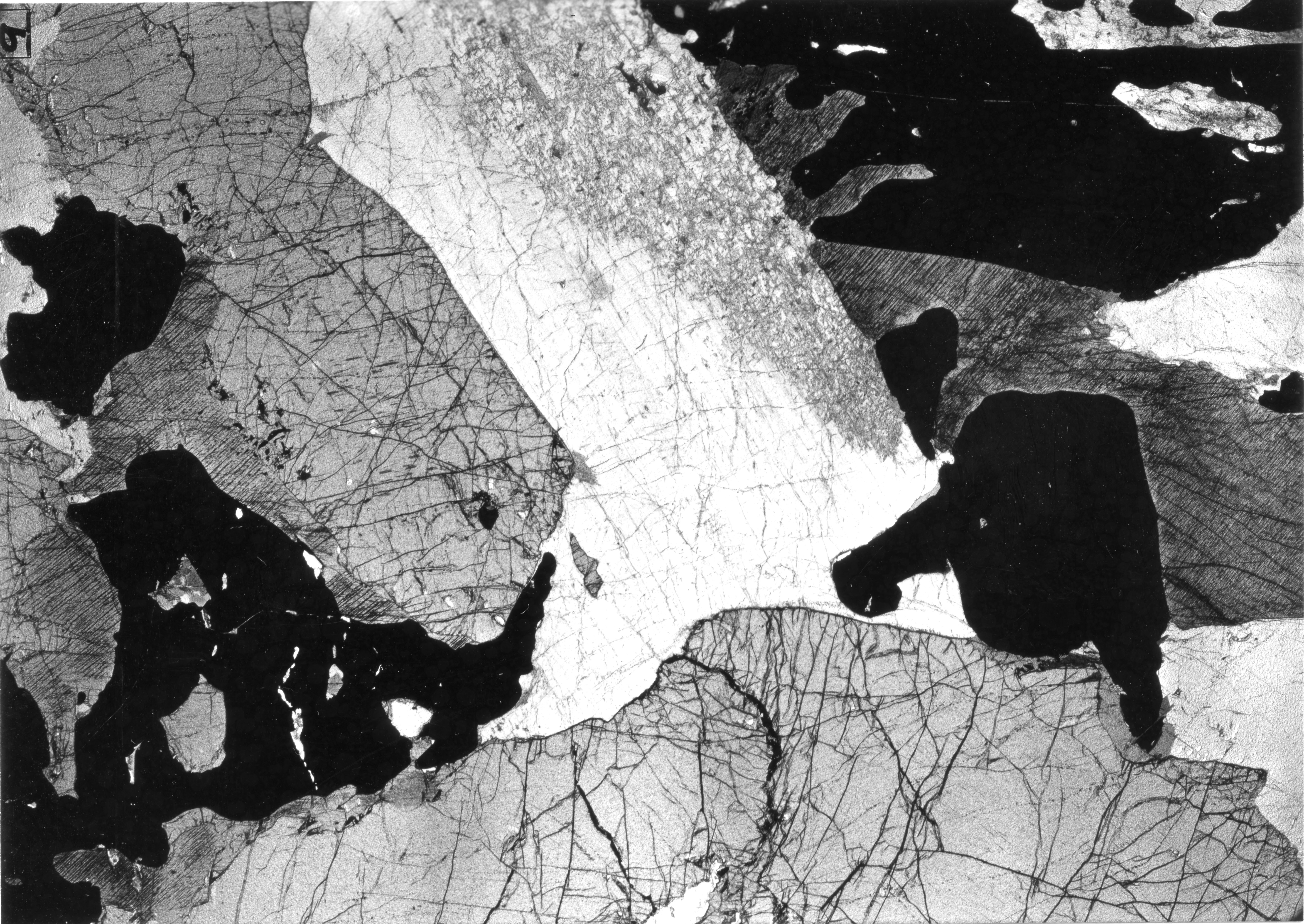
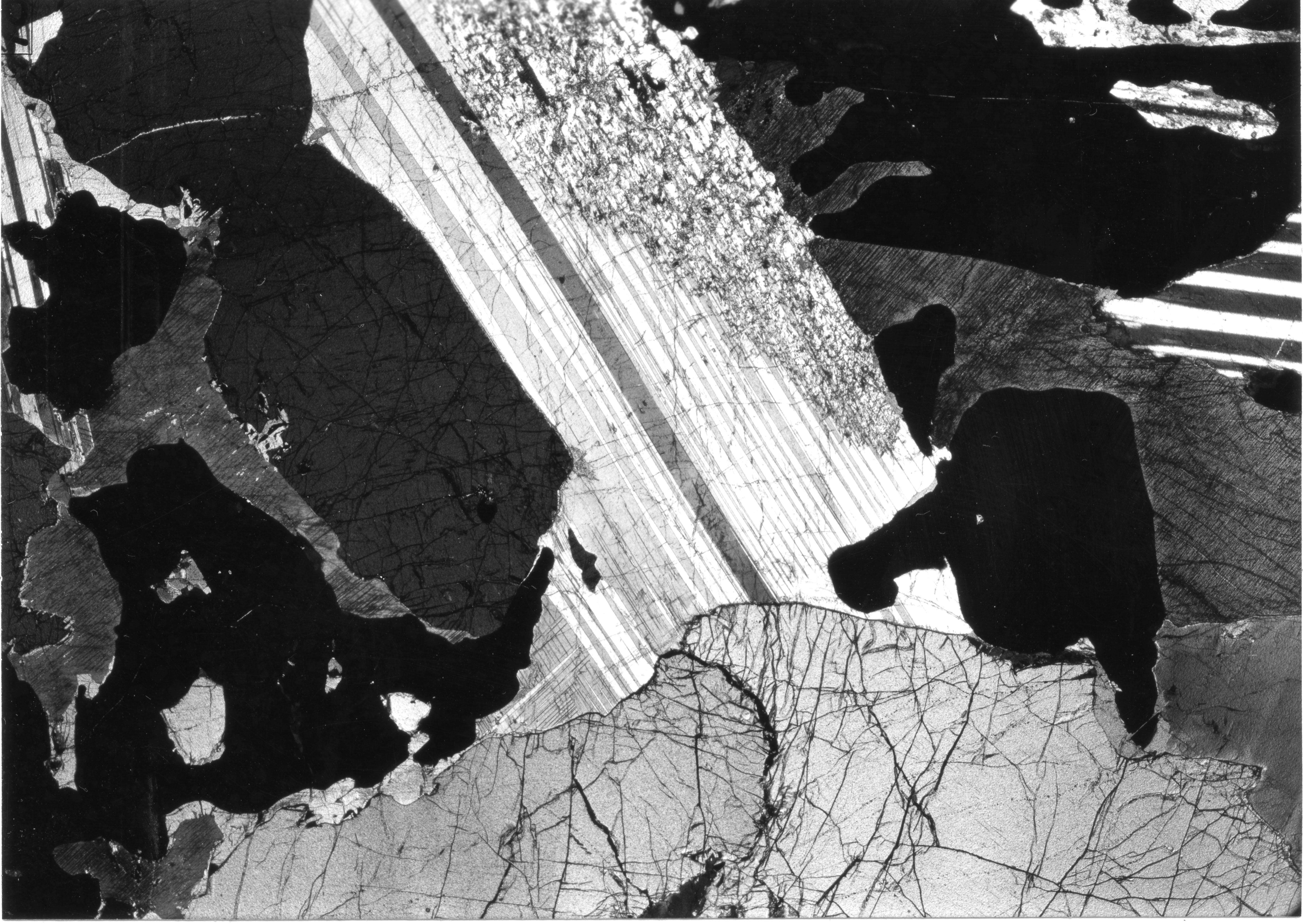
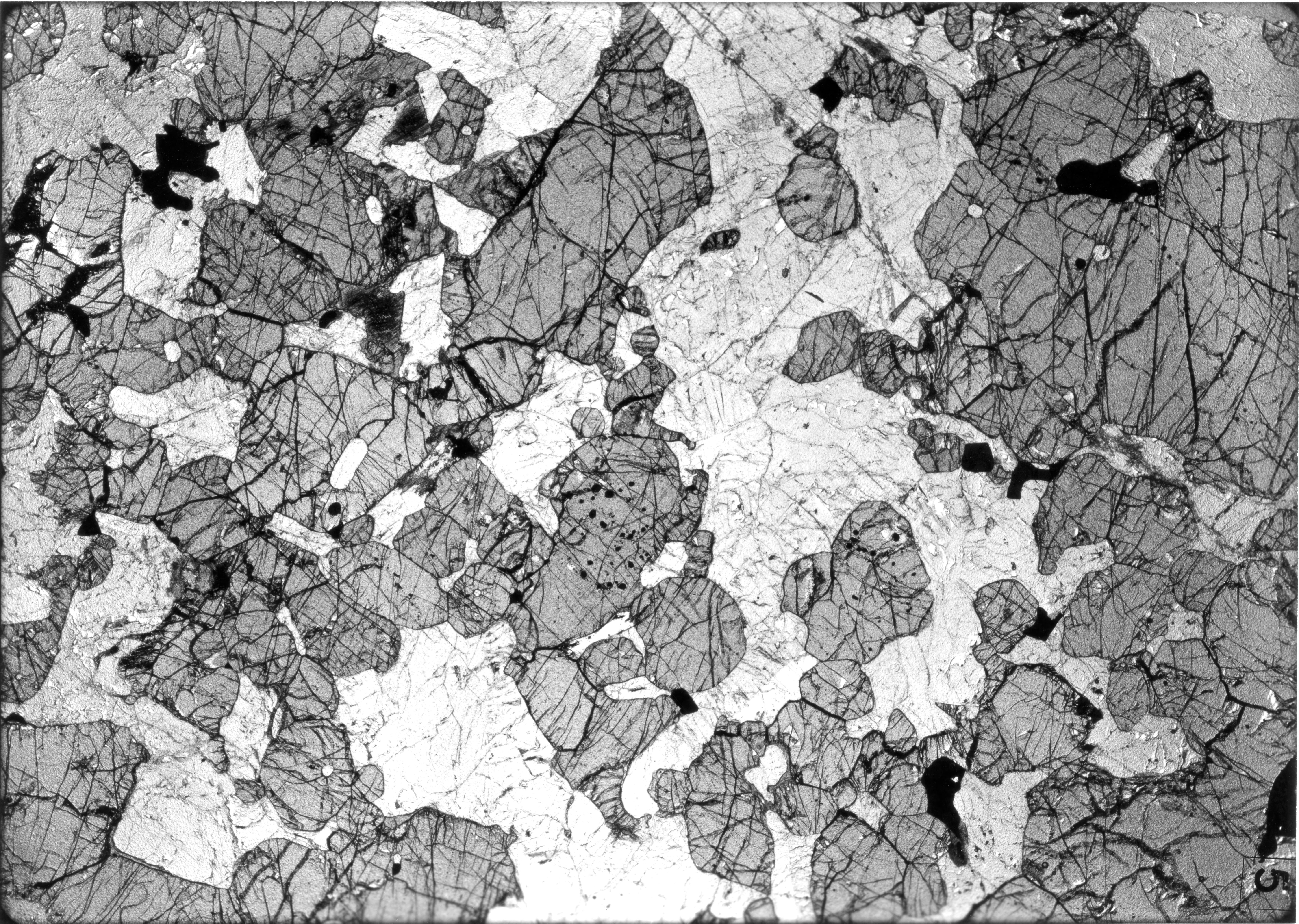
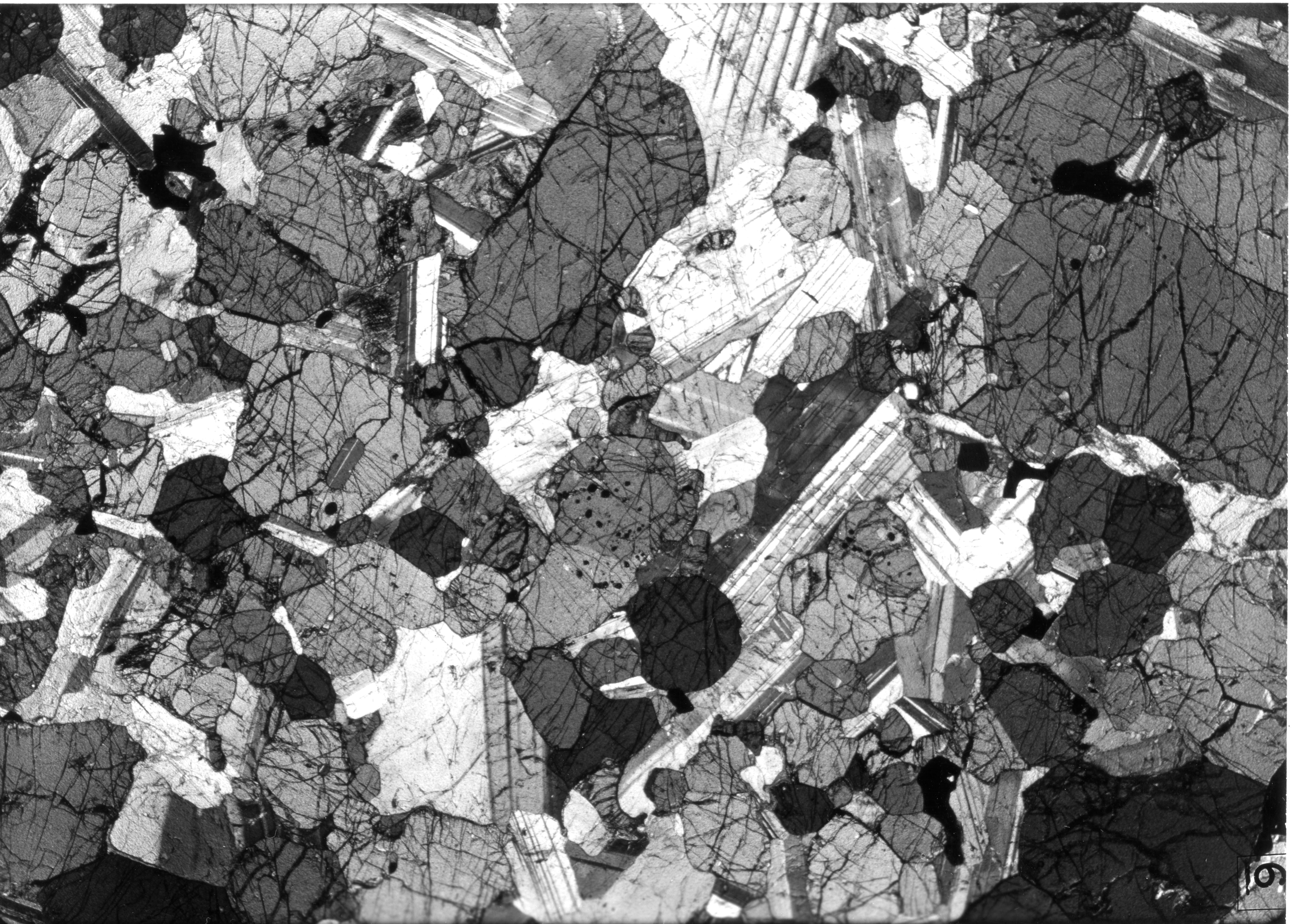
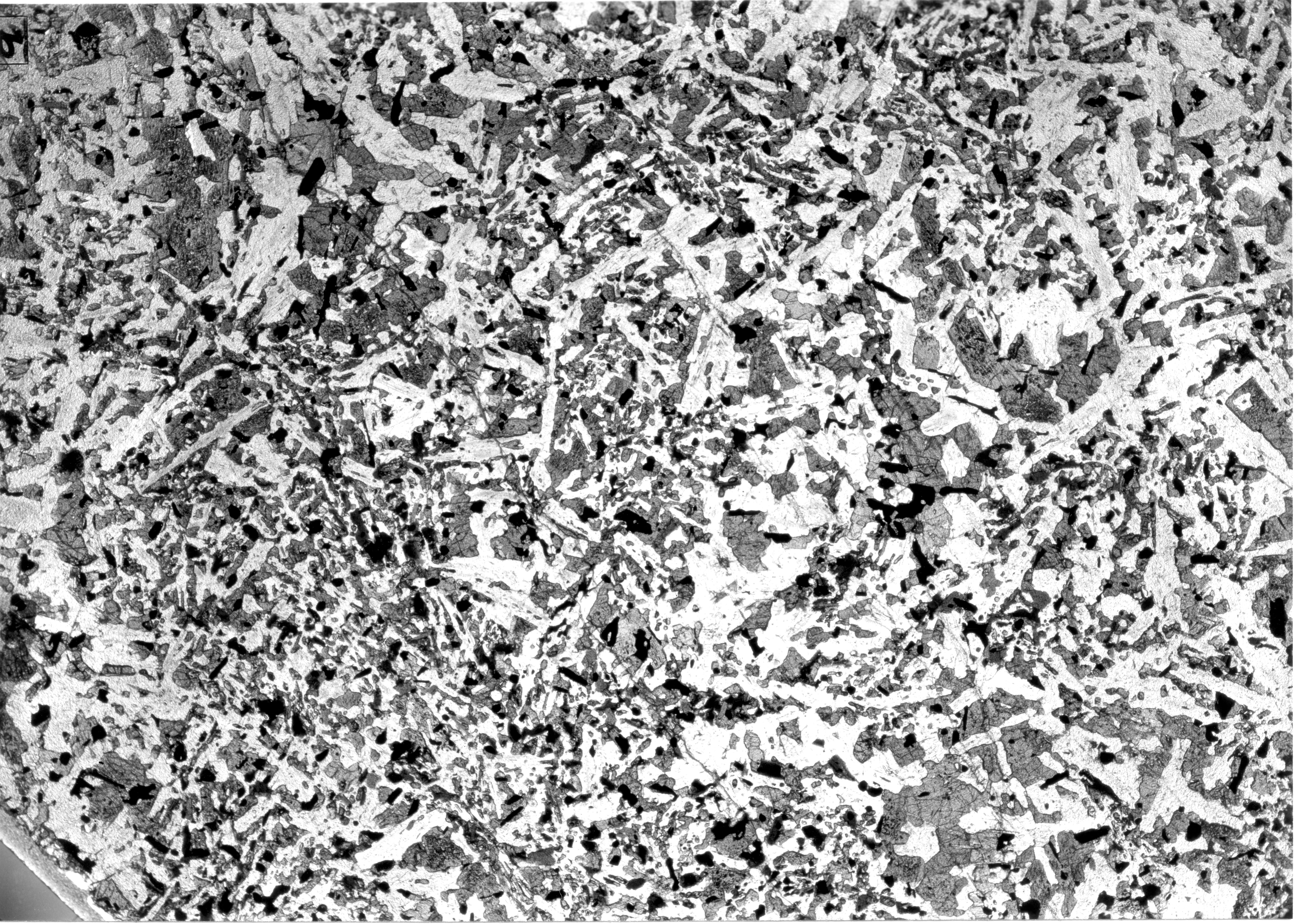
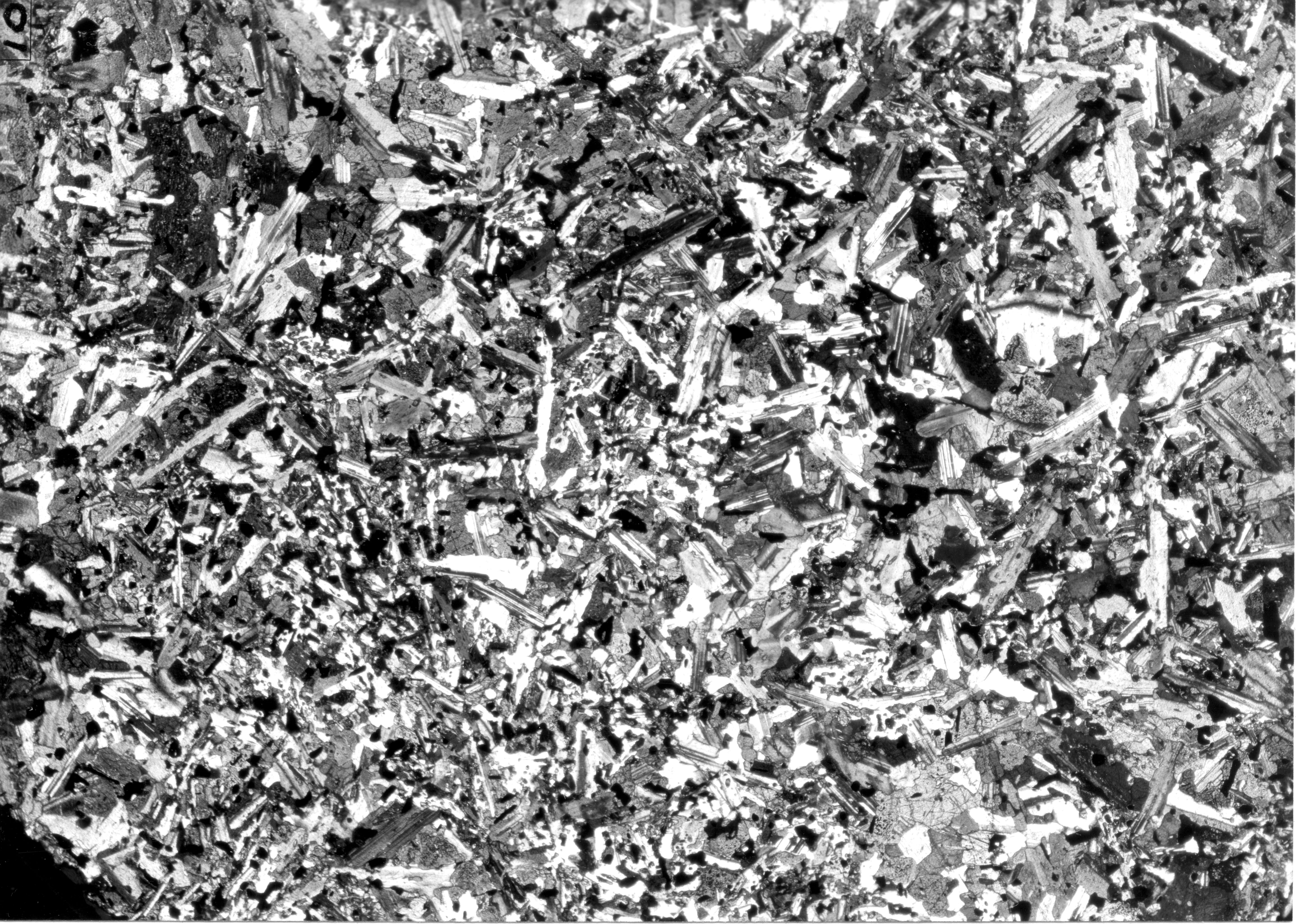
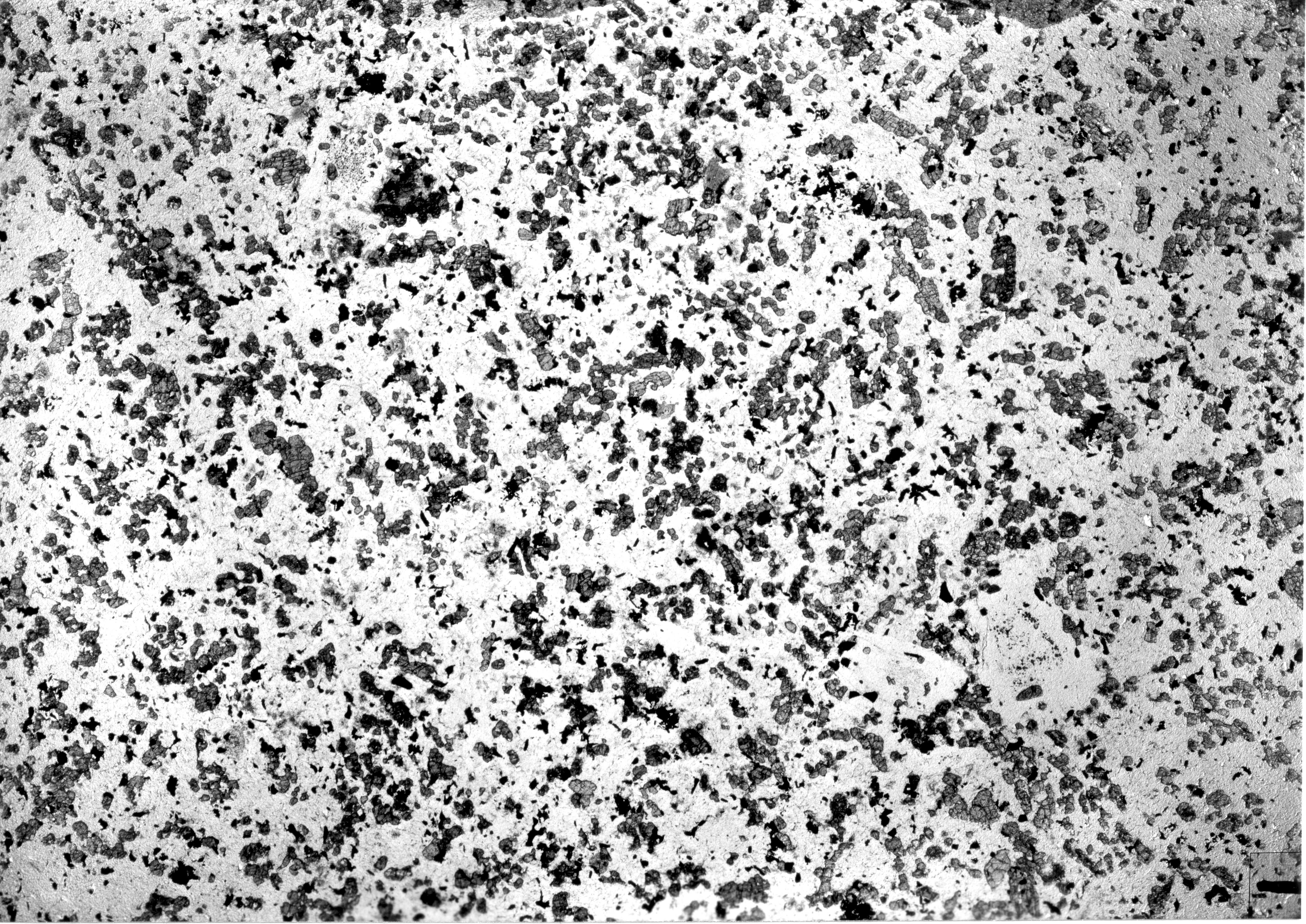
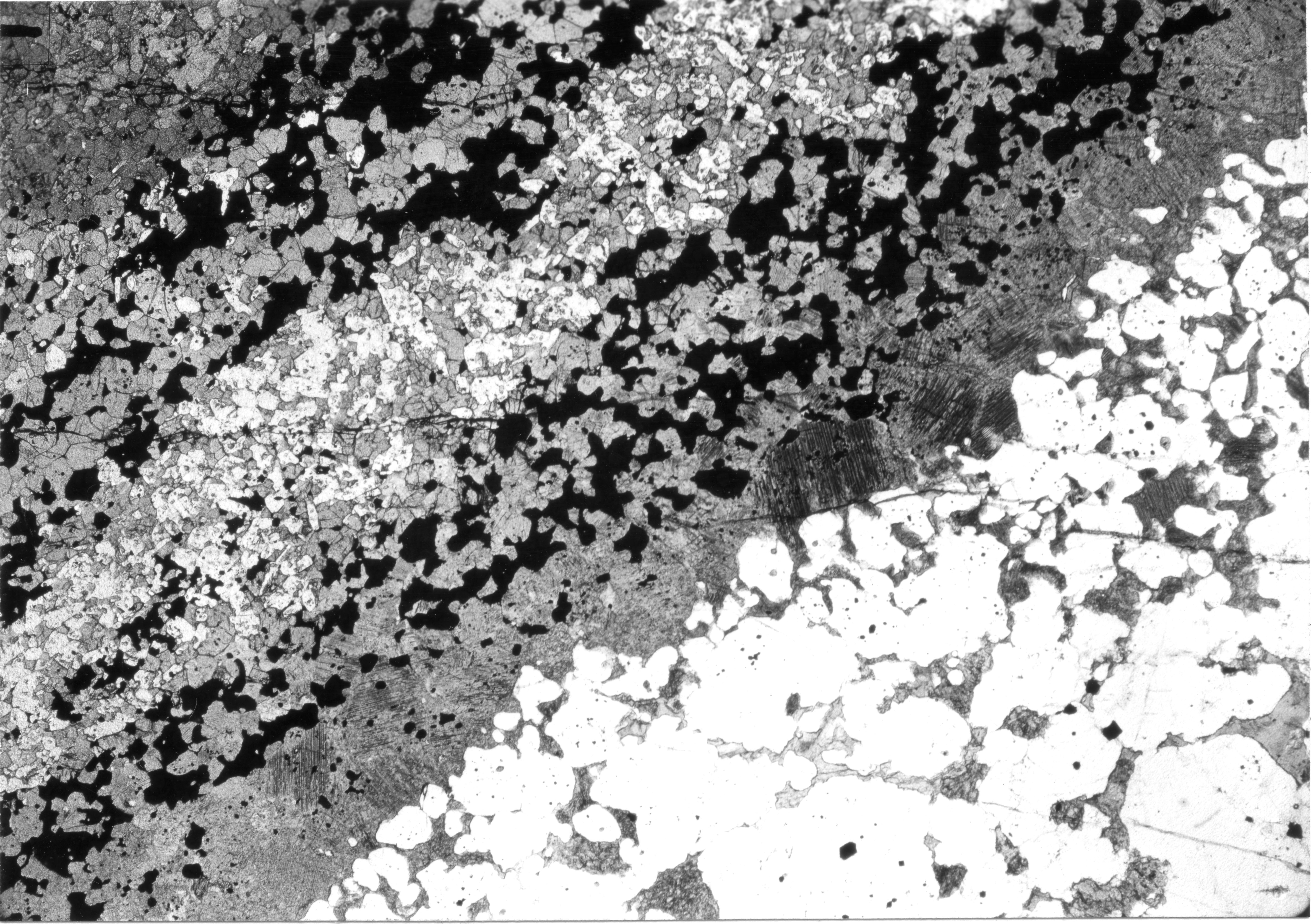
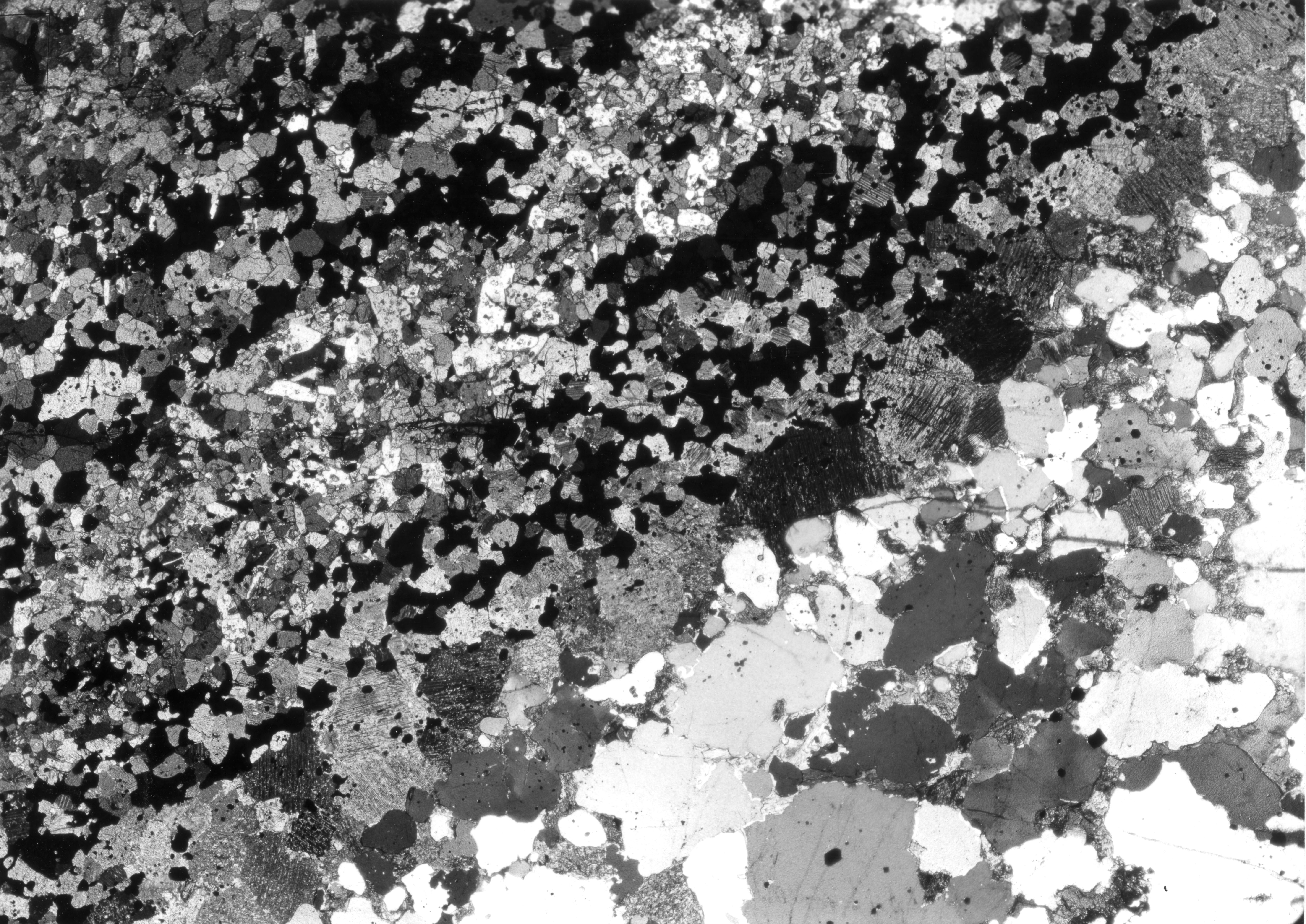
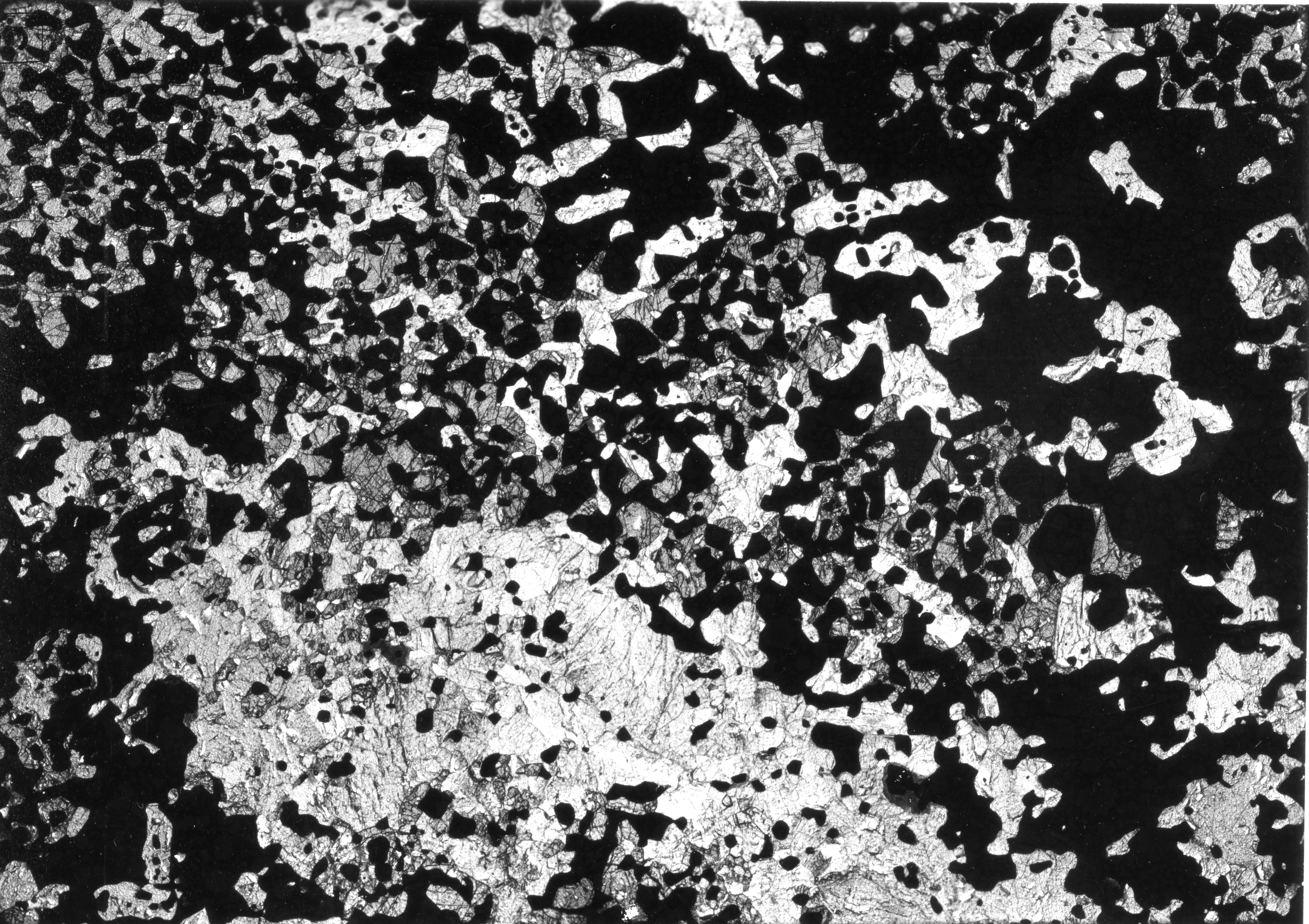
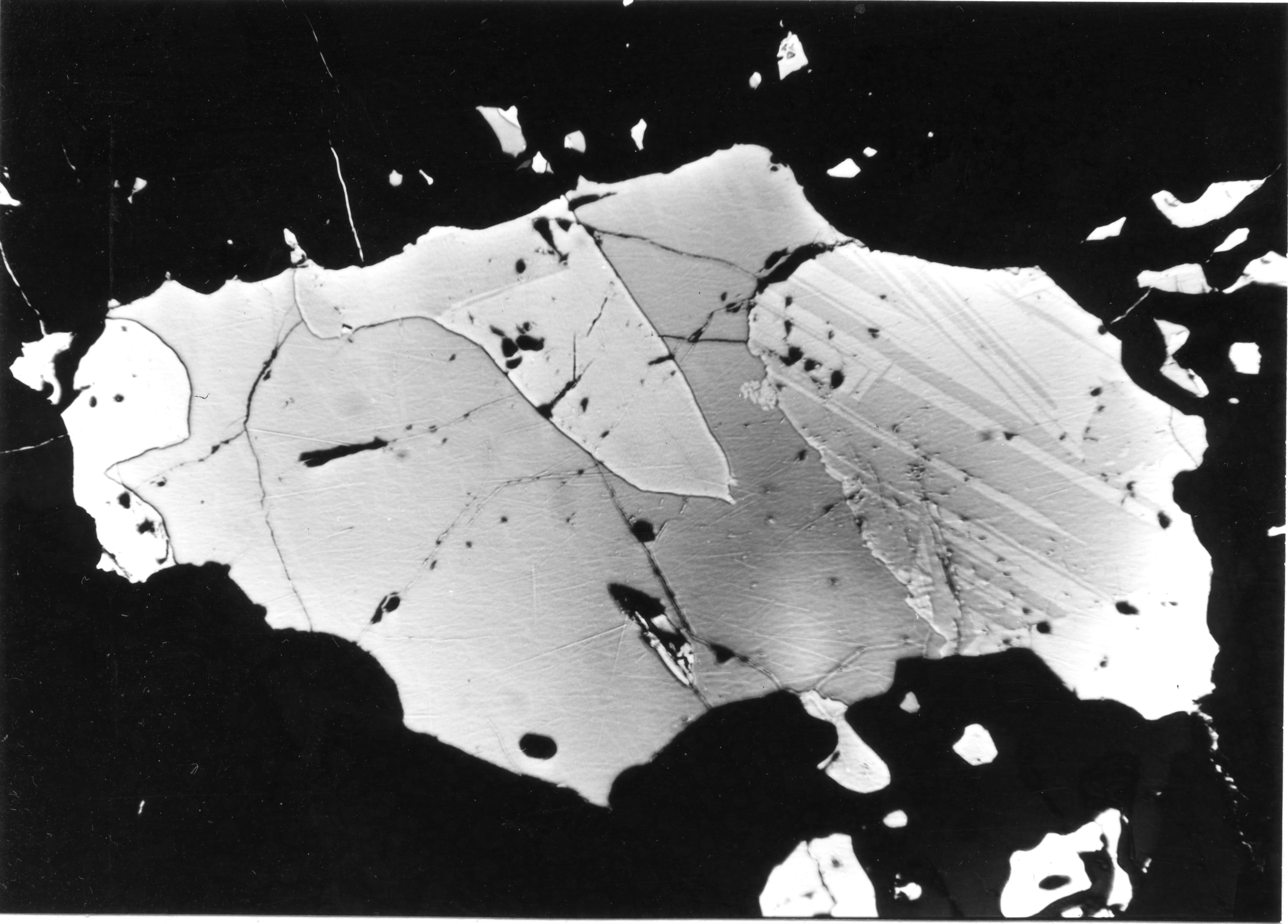
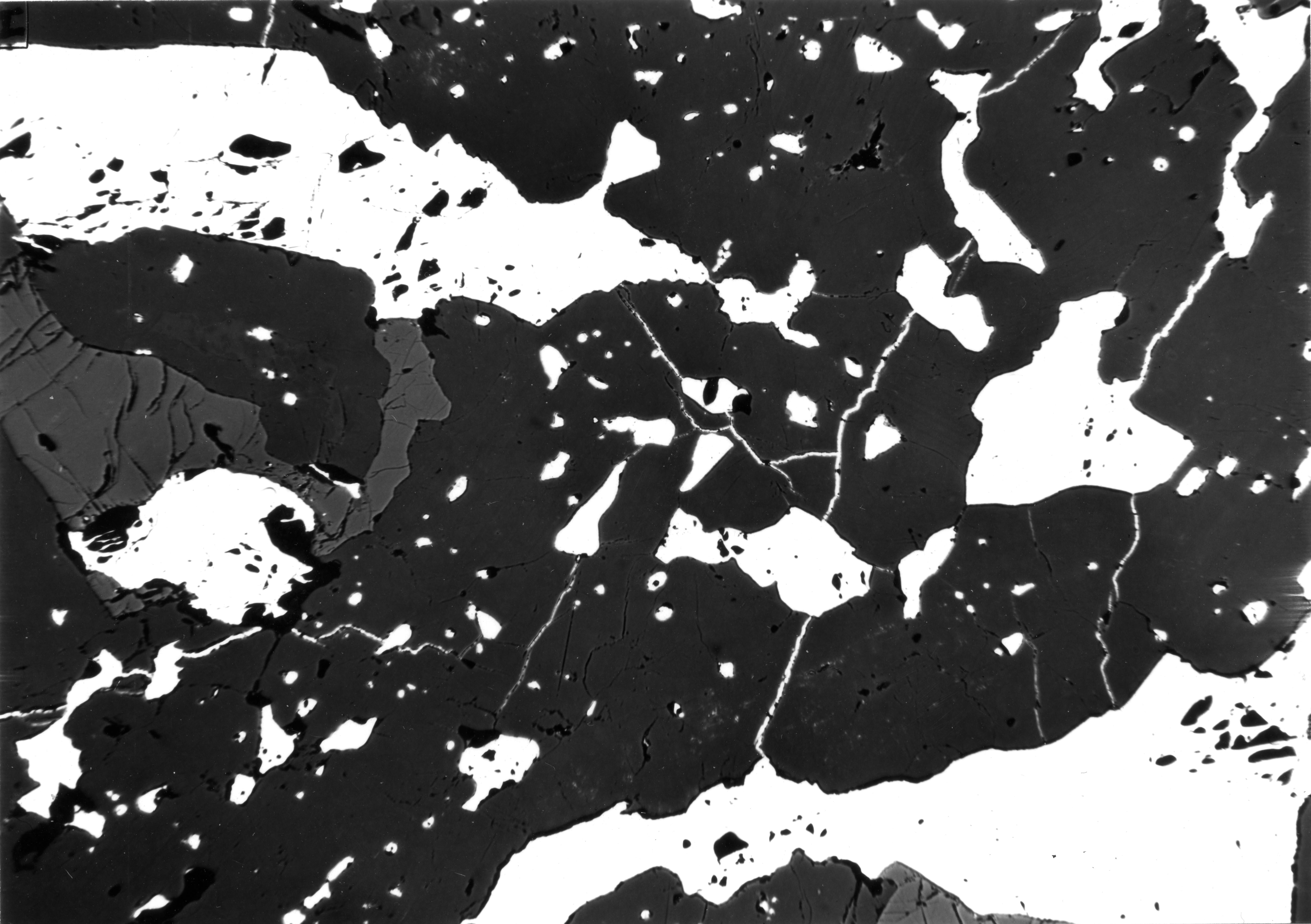
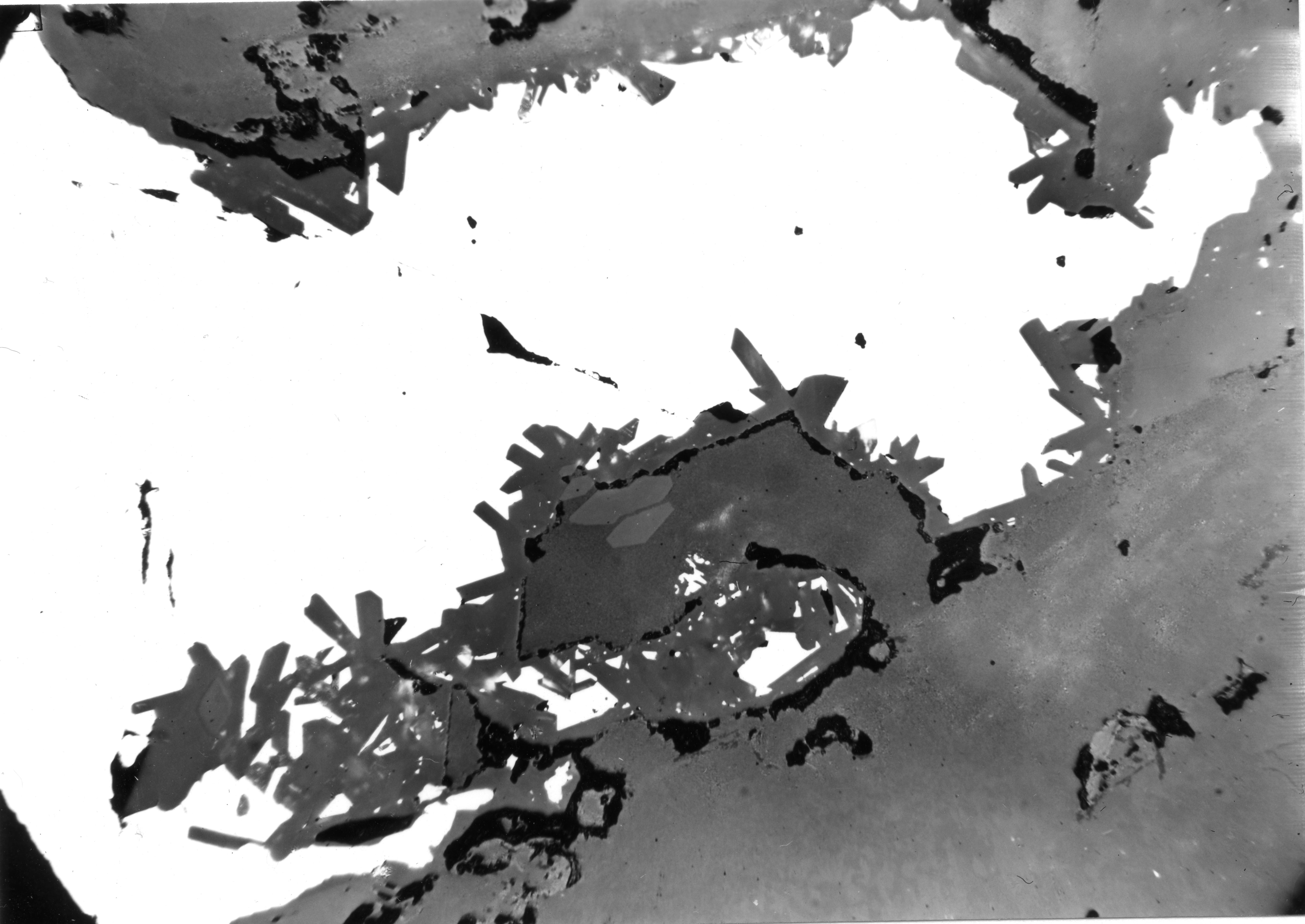
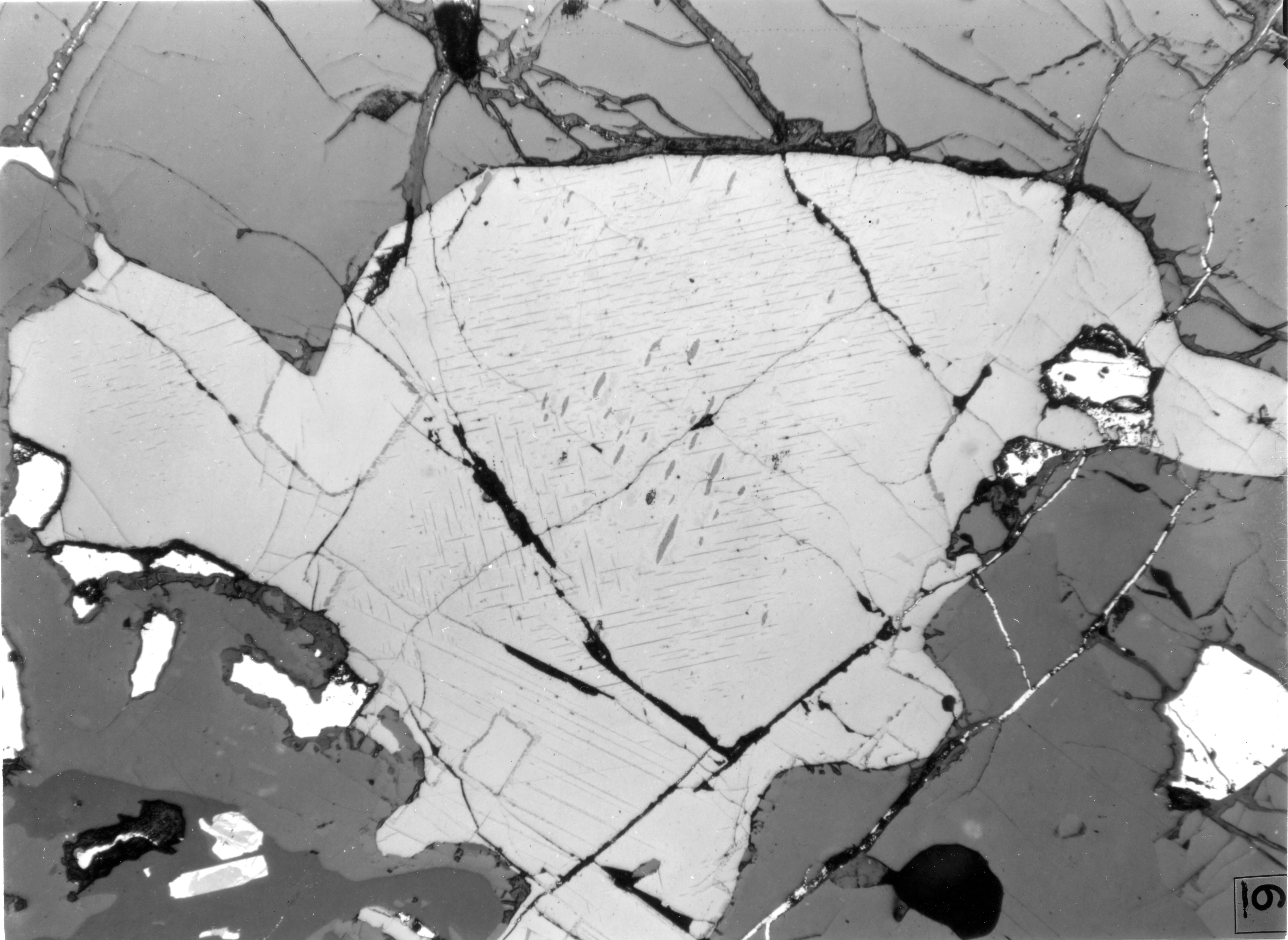
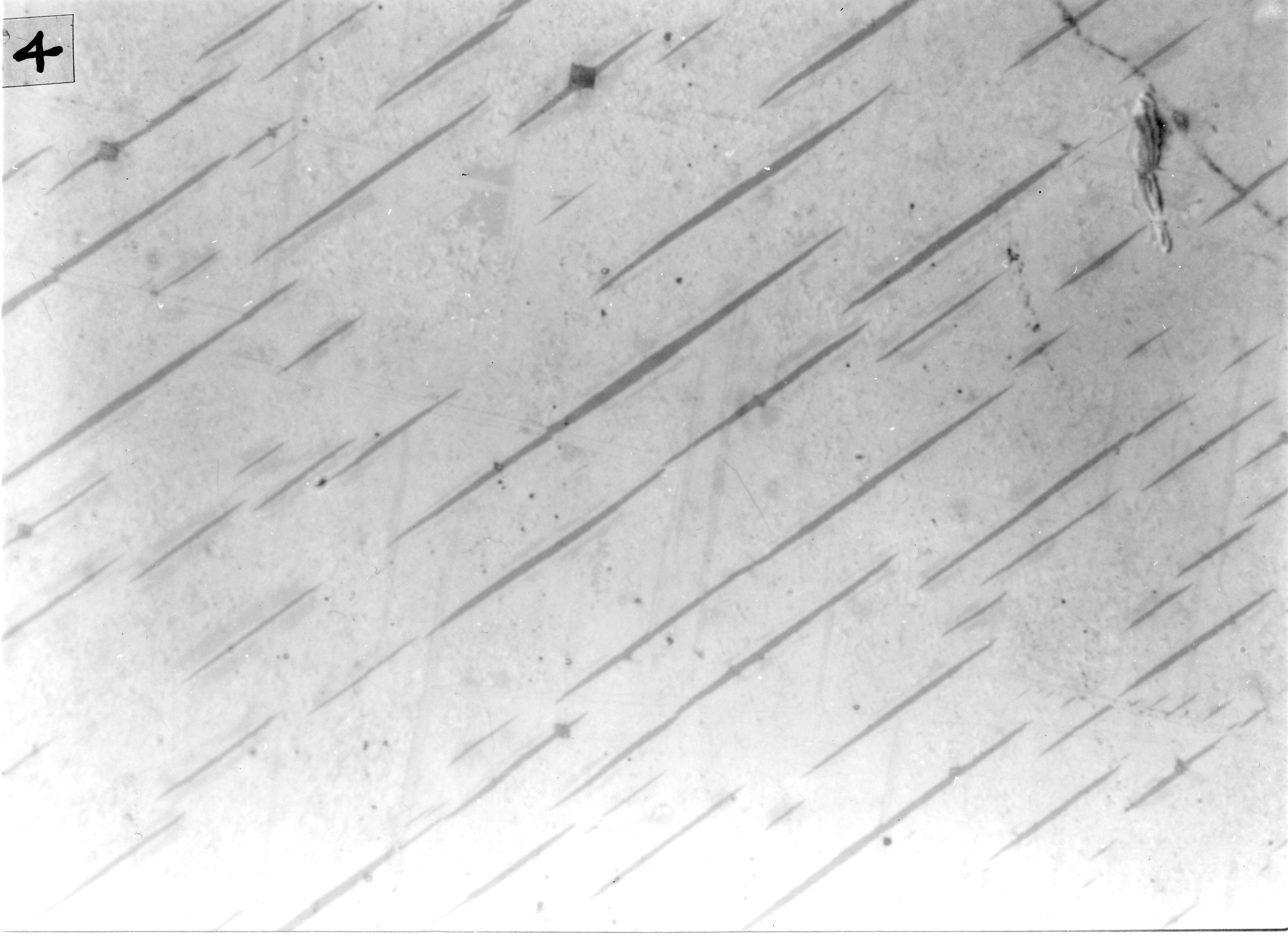
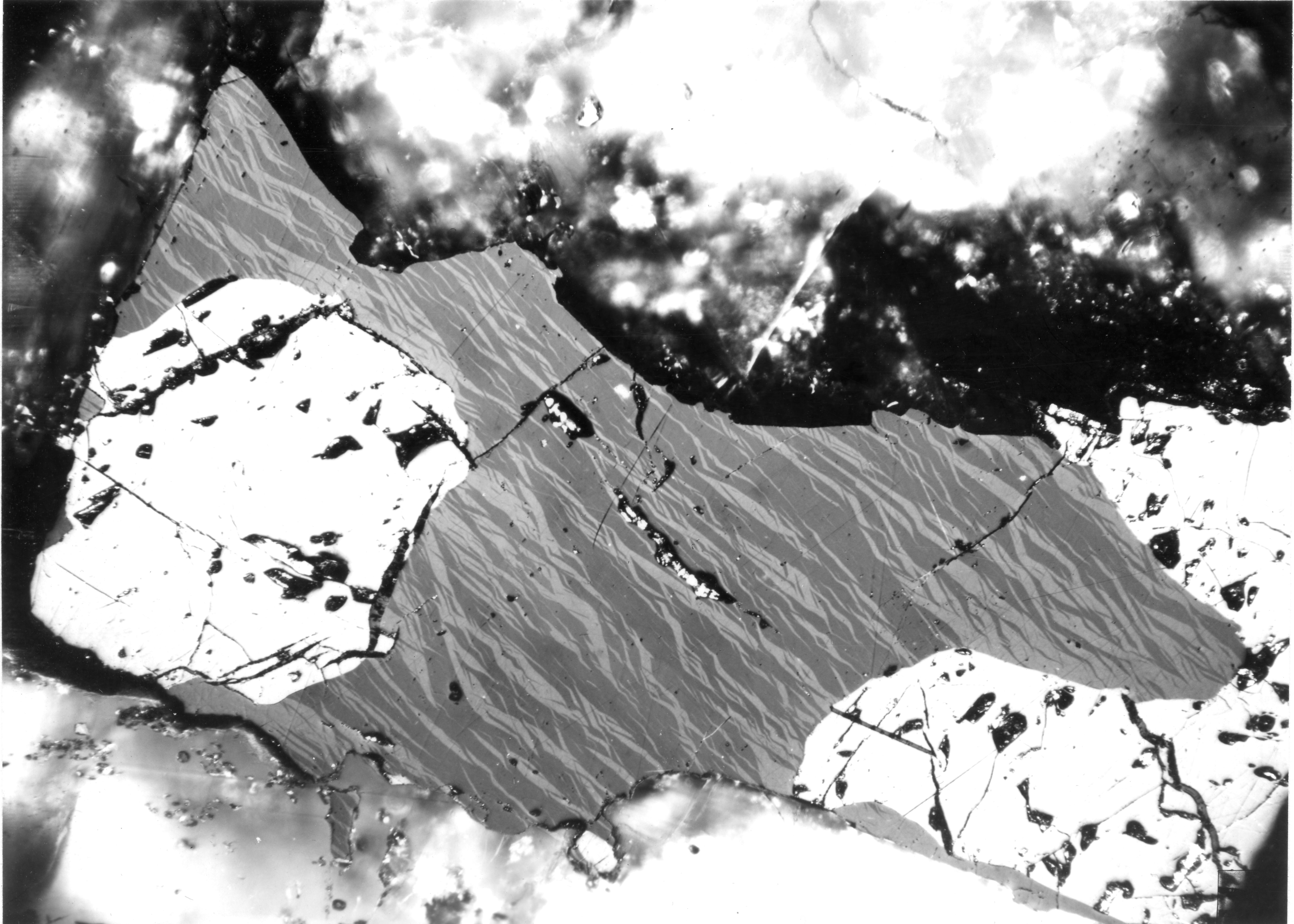
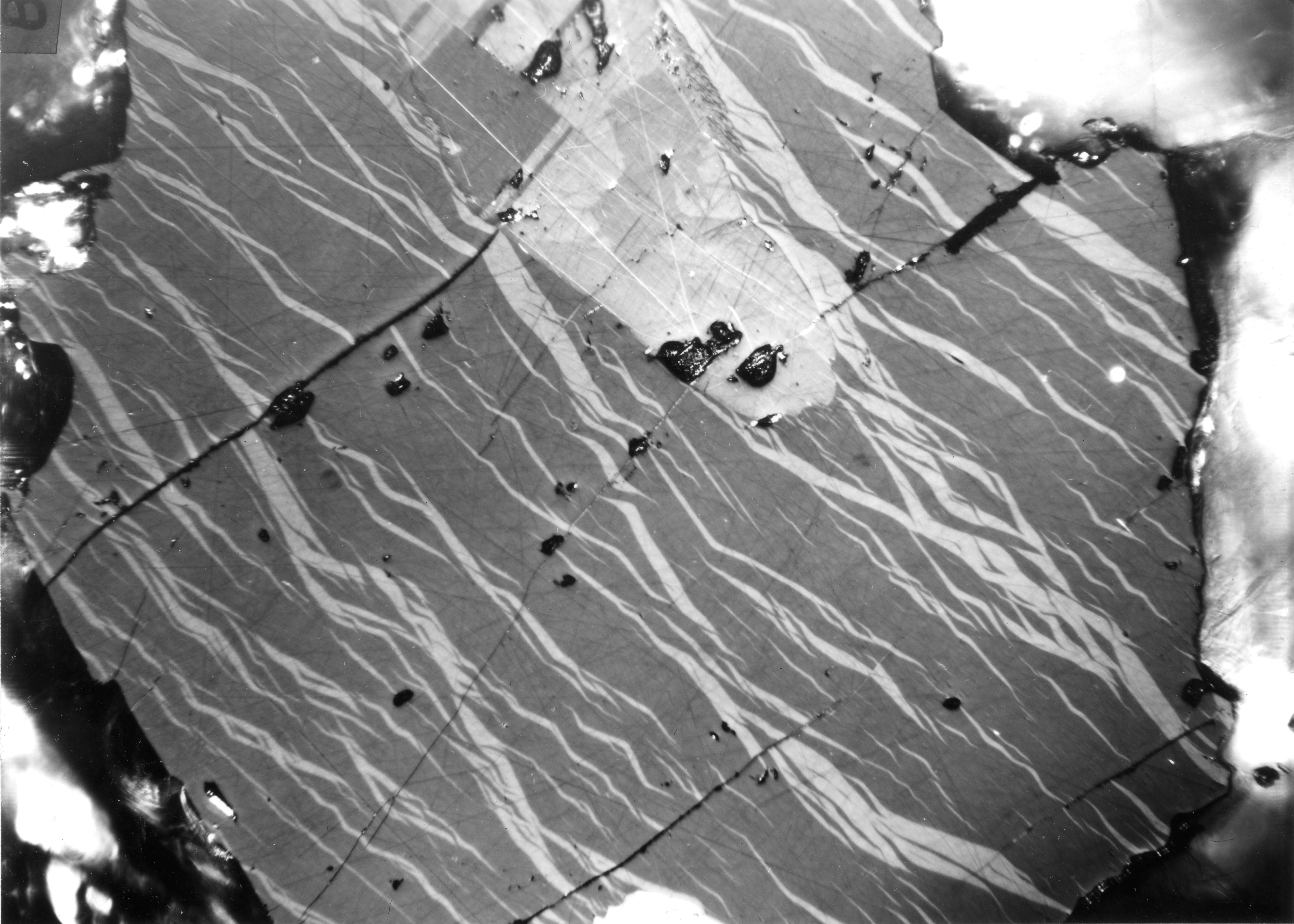
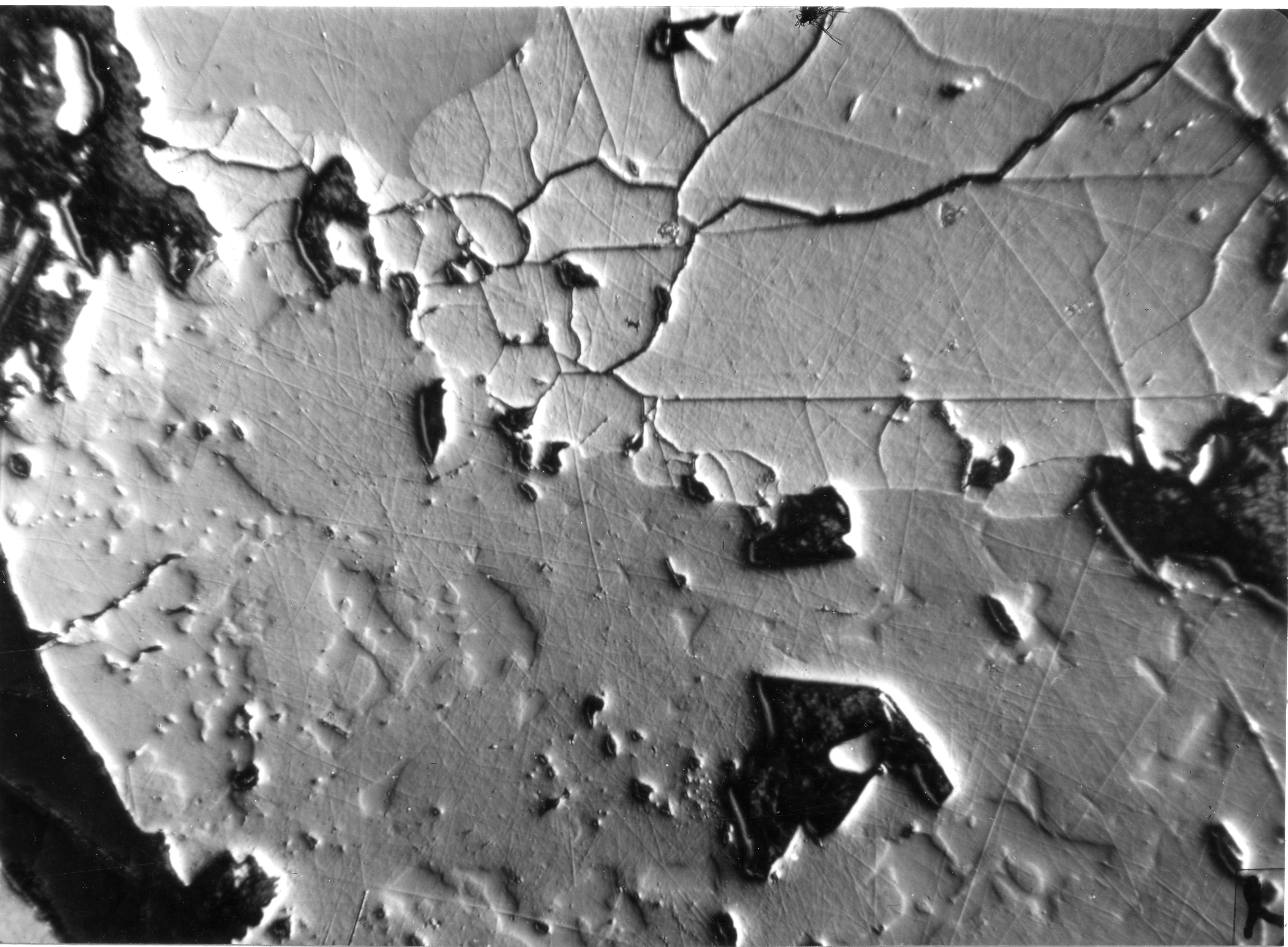
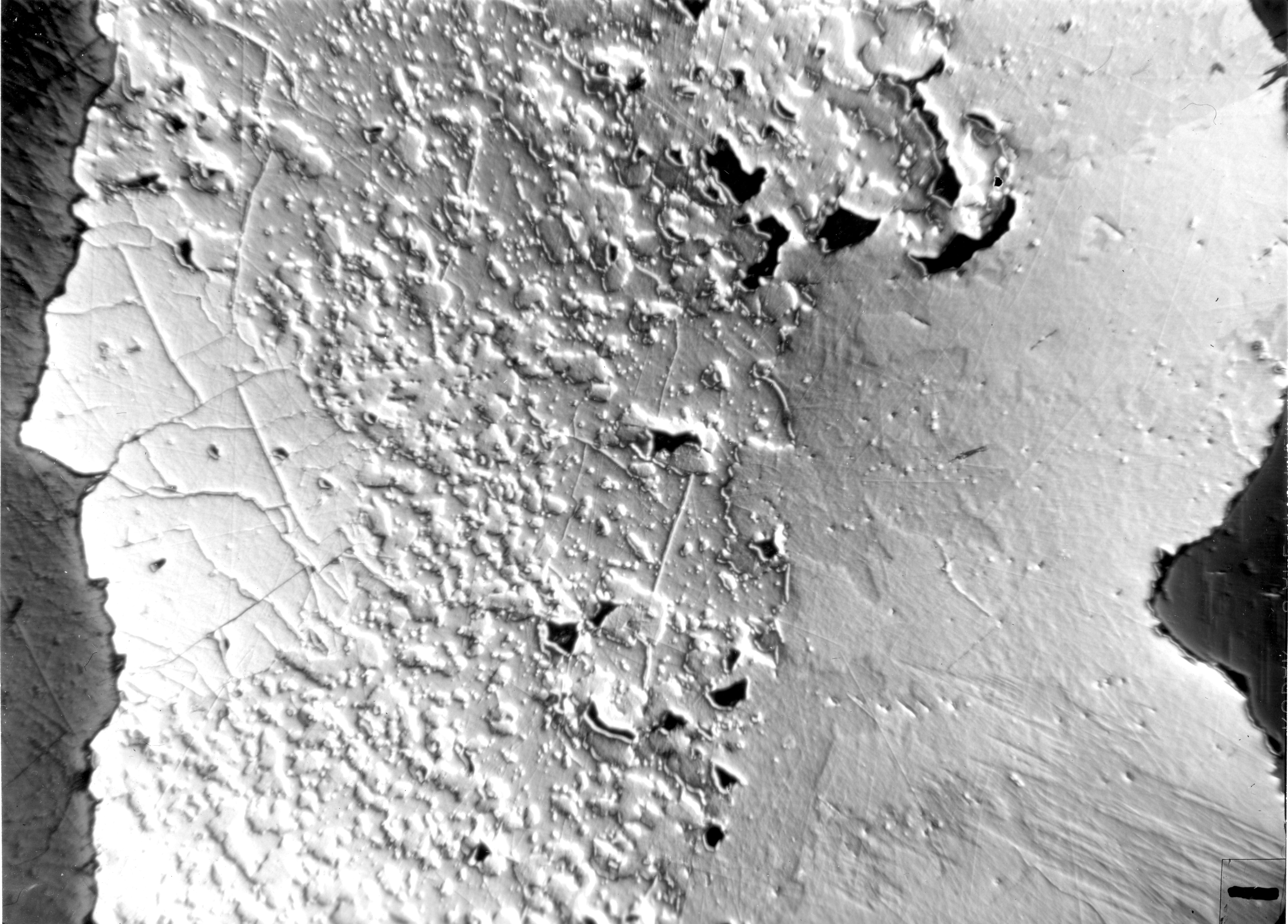
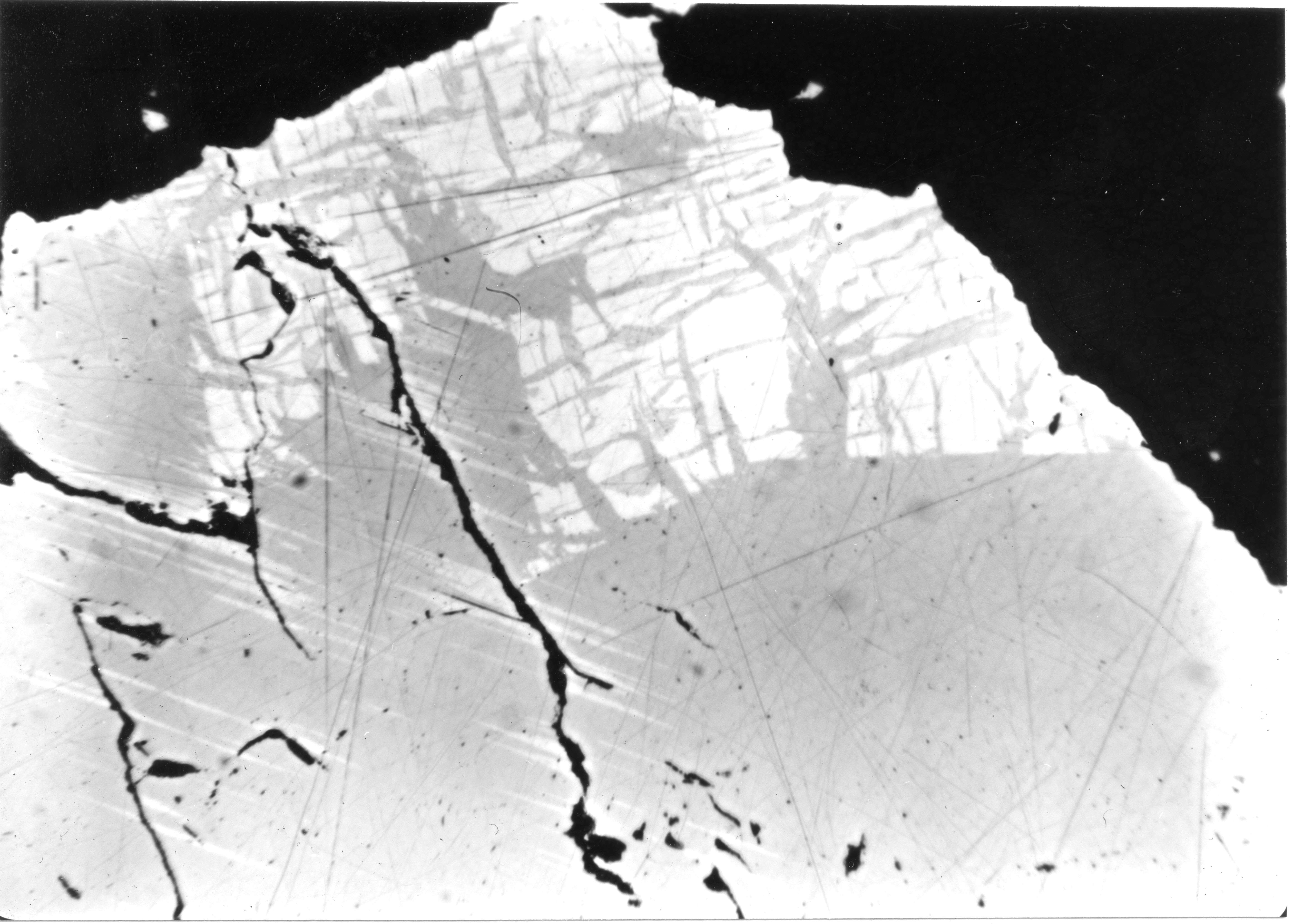
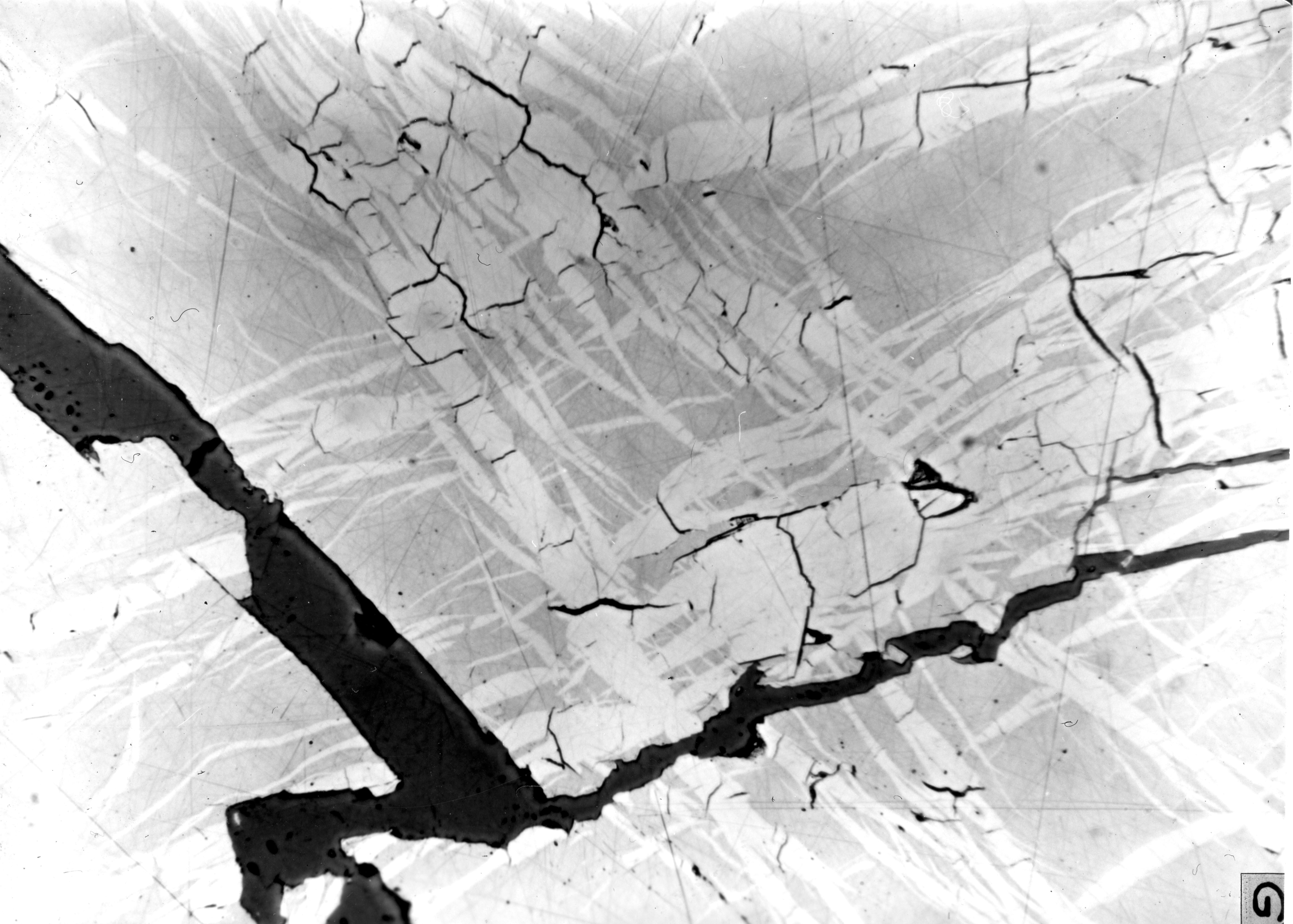
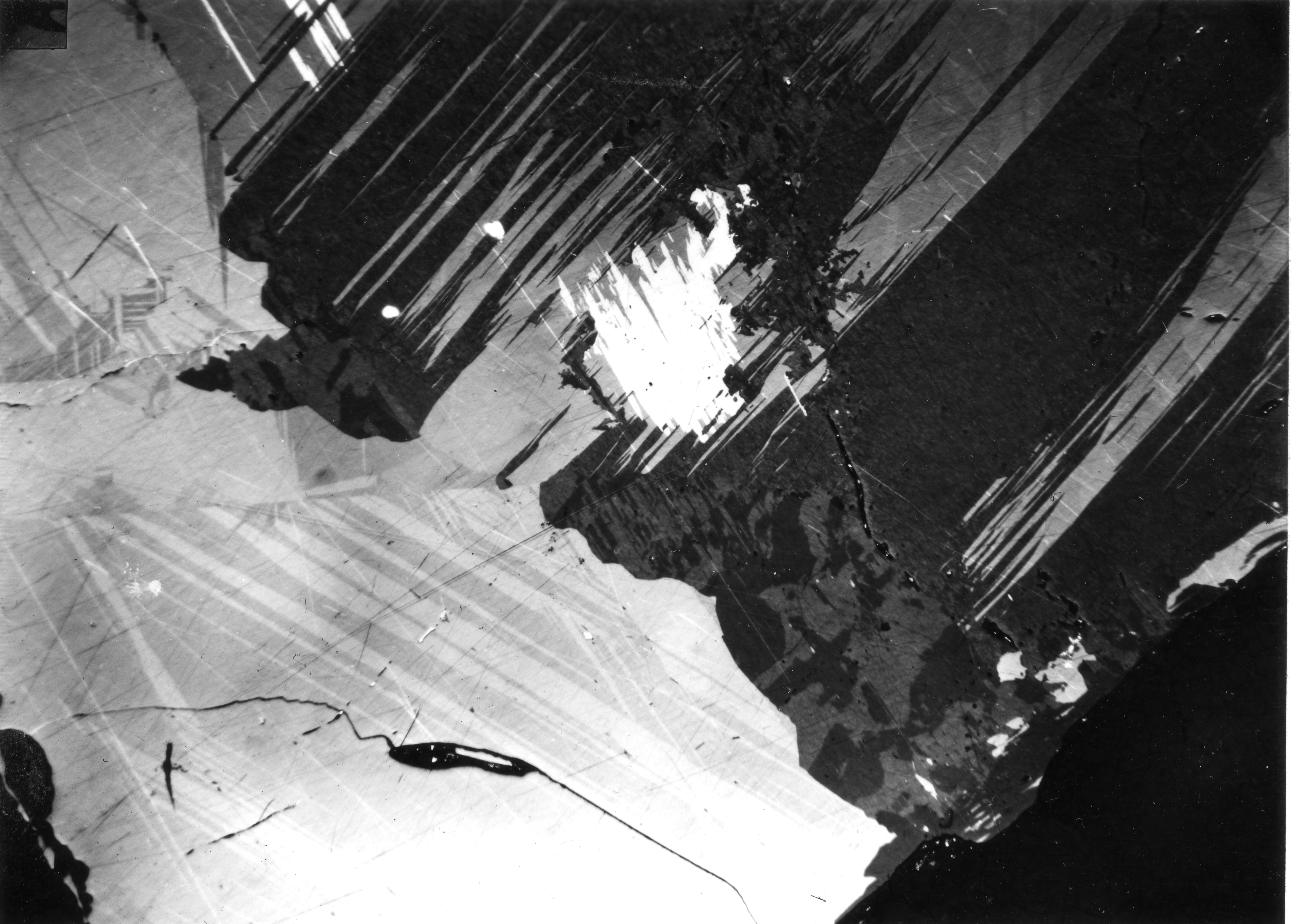
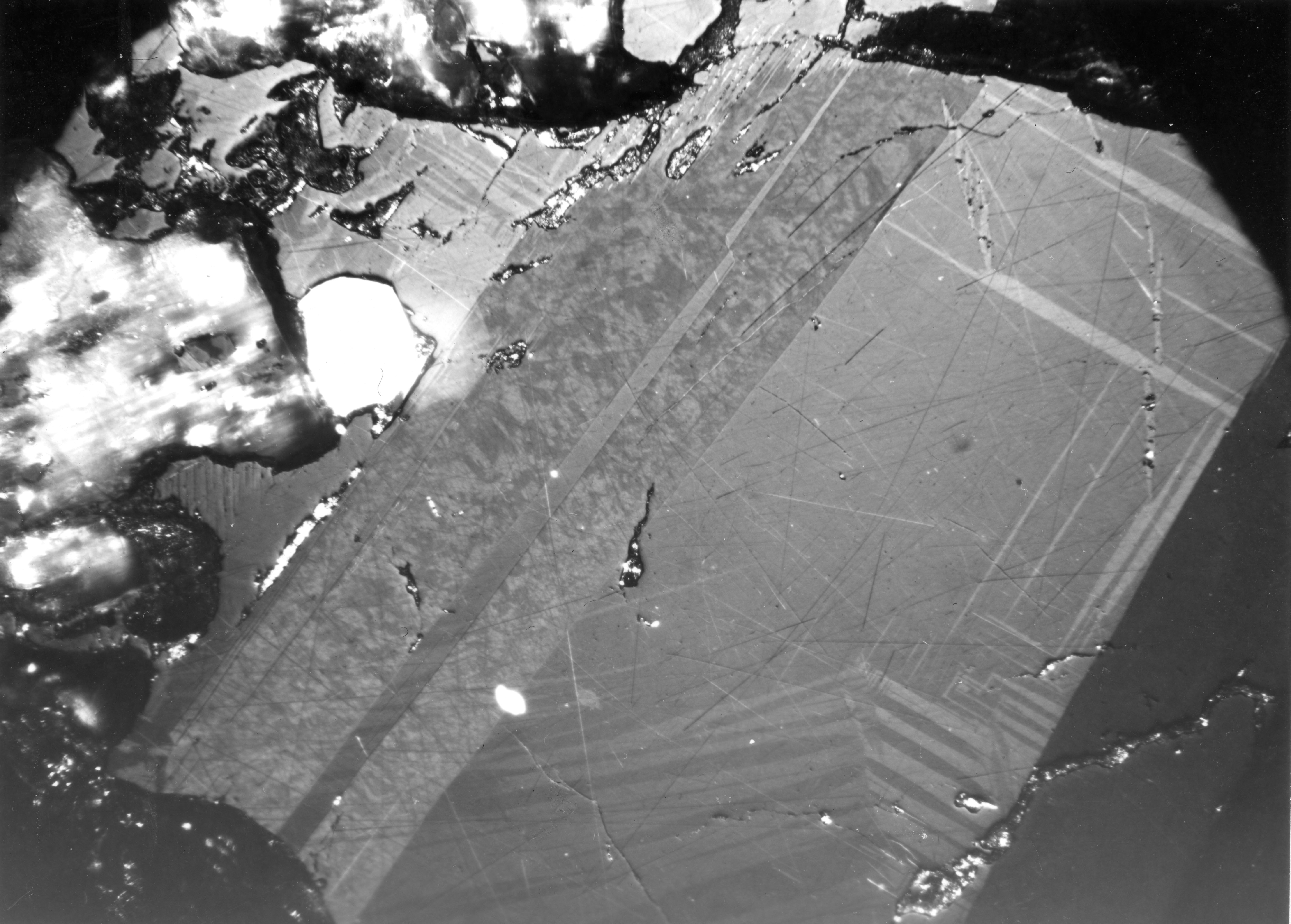
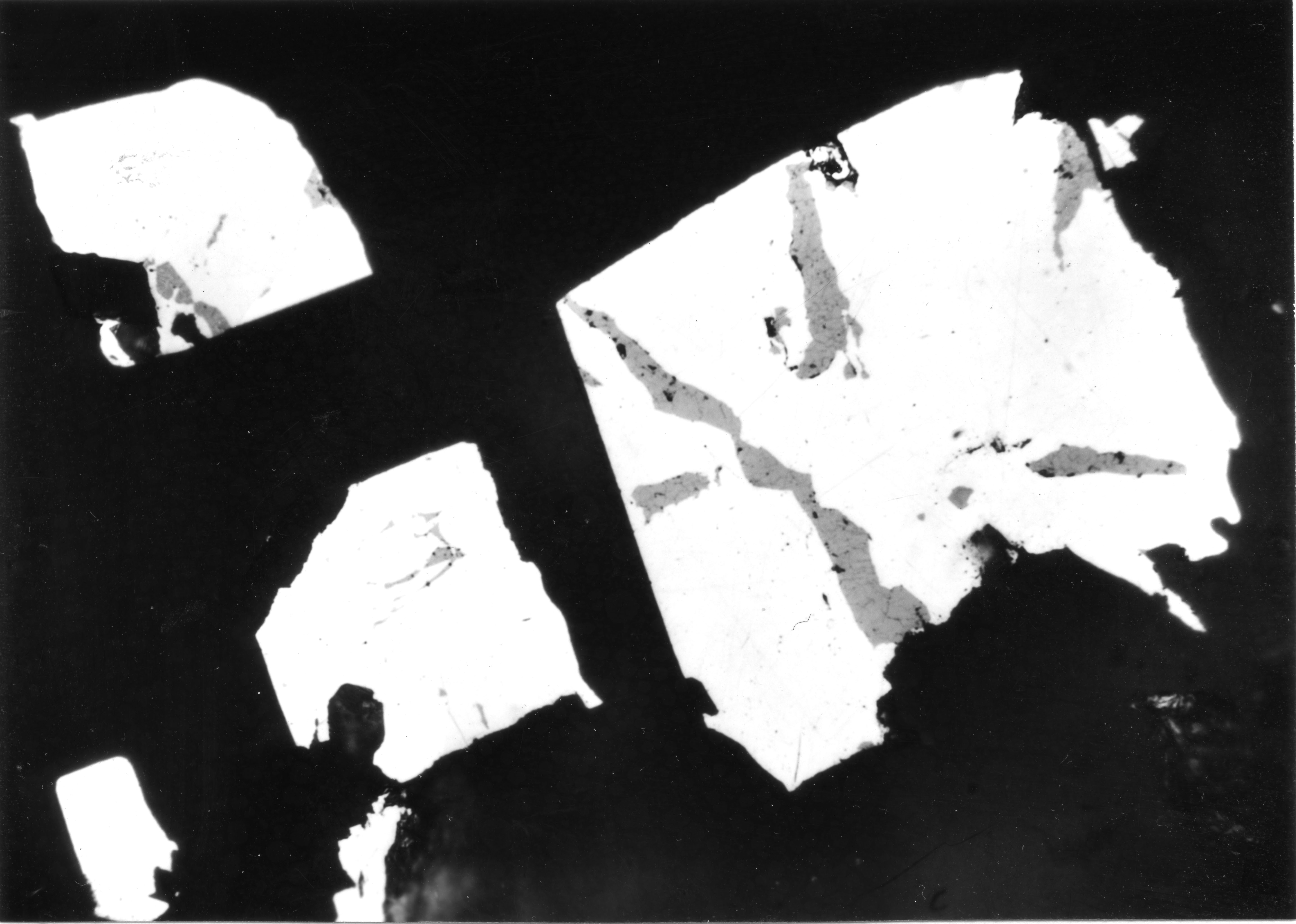
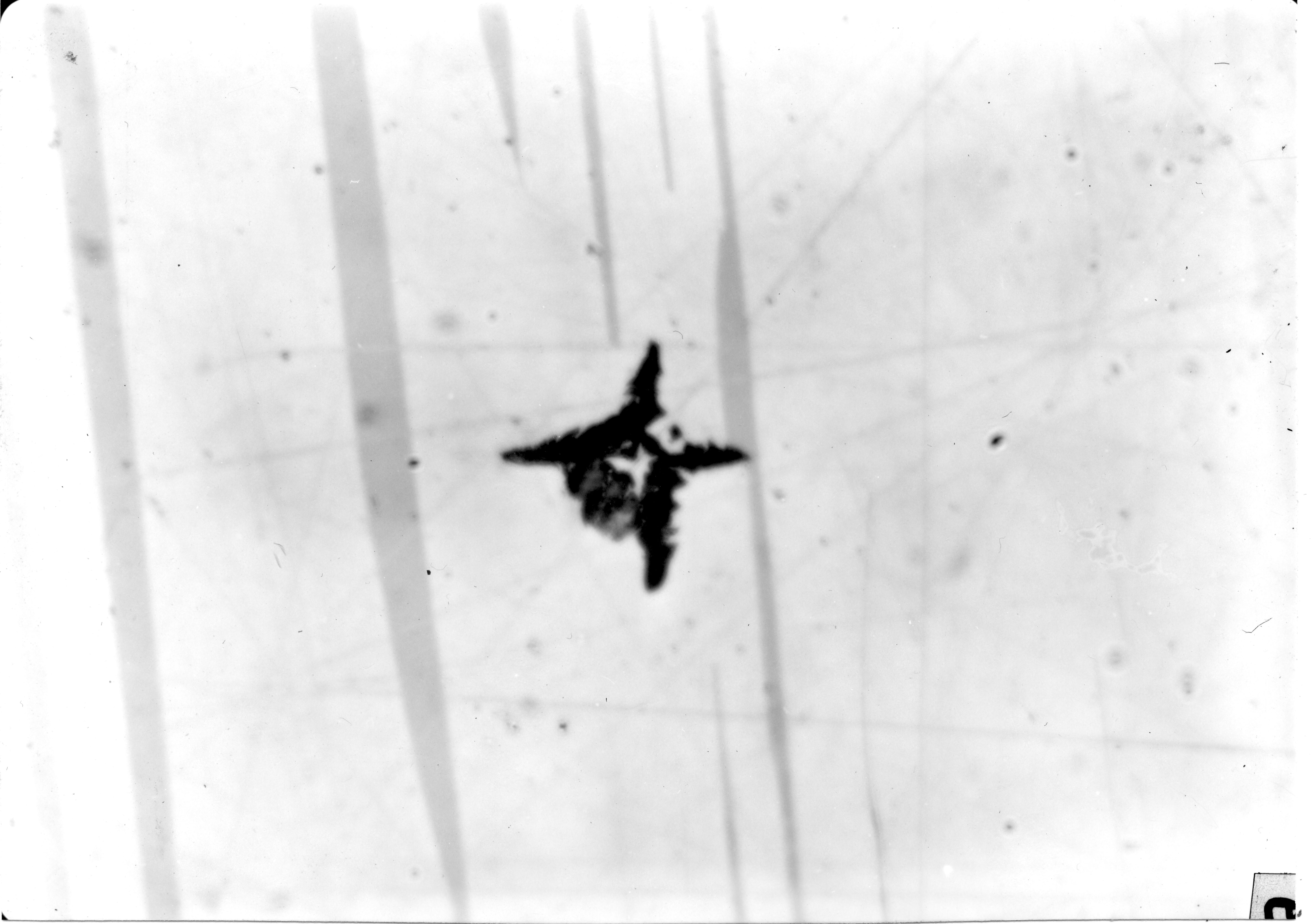
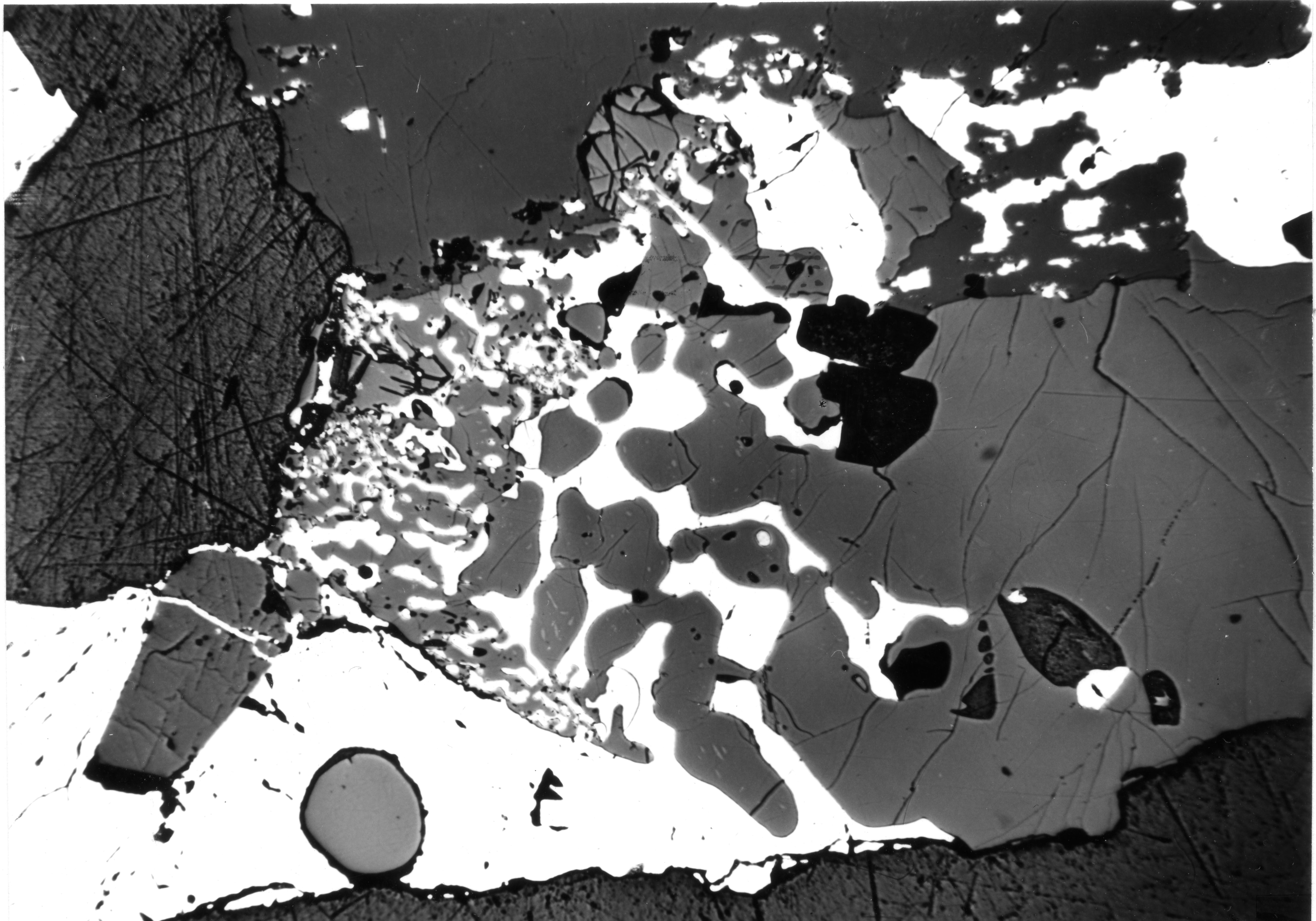